Advertisement
For questions on assembly or for general inquiries, you may contact us in the following ways:
Call a Recruiter Today! 734-365-7000
Flexible schedule
*based on number of completed installations
Call Us First!
DO NOT RETURN TO STORE.
Call customer service: 1-877-743-3400
AVOID THE WAIT!
visit us online at
help.backyardproducts.com
Submit a help request
Answers to frequently asked questions
Live chat with an agent
Did you enjoy building your shed?
JOIN OUR TEAM
AND MAKE UP TO $1,500/WEEK*
No selling,
just building
Bonus incentives
available
16583-P
Advertisement
Table of Contents

Related Manuals for Yardline BRAXTON


Summary of Contents for Yardline BRAXTON
- Page 1 16583-P Call Us First! DO NOT RETURN TO STORE. For questions on assembly or for general inquiries, you may contact us in the following ways: Call customer service: 1-877-743-3400 AVOID THE WAIT! visit us online at help.backyardproducts.com Submit a help request Answers to frequently asked questions Live chat with an agent Did you enjoy building your shed?
- Page 2 (This page intentionally left blank.)
-
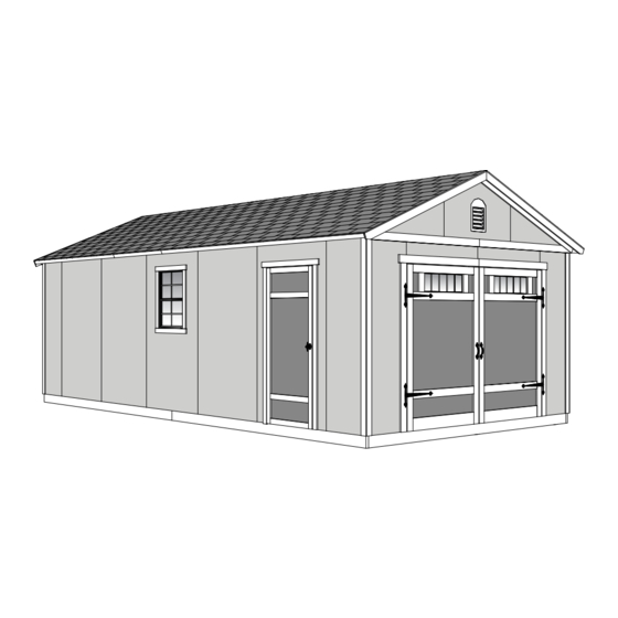
Page 3: Assembly Manual
16583-P 07/11/2019 ASSEMBLY MANUAL A Backyard Products Company BRAXTON 12' x 24' (365,7 x 731,5 cm) Actual foor size: 144" x 288" (365,7 x 731,5 cm) KEEP THIS MANUAL FOR FUTURE REFERENCE I M PO RTANT! READ INSTRUCTIONS THOROUGHLY PRIOR TO BEGINNING ASSEMBLY. - Page 4 IMPORTANT! AN OVERHEAD DOOR IS NOT AVAILABLE FROM YARDLINE! USE INSTRUCTIONS SUPPLIED WITH THE DOOR MANUFACTURER TO FRAME-IN YOUR FRONT WALL DOOR OPENING. **PROVIDE THIS PAGE TO THE DOOR MANUFACTURER** Additional trim required (213,3 cm) Wall Height Threshold Required (365,7 cm)
- Page 5 TOOLS Required Optional ❑ Phillips ❑ Utility Knife ❑ Tool Belt/ Screwdriver Nail Pouch ❑ Shingle Blades ❑ Drill / Driver ❑ Caulk Gun ❑ Tin Snips ❑ 3/8" Drill Bit (for drip edge) ❑ #2 Philips Drive Bit ❑ Chalk Line ❑...
- Page 6 ADDITIONAL MATERIALS THIS KIT DOES NOT INCLUDE ANY FOUNDATION OR FLOOR MATERIALS. See page 5 for a CONCRETE FOUNDATION option. See pages 6 to 13 for a WOOD FLOOR framing option. See the FLOOR LEVELING section on page 7 for recommended methods and suggested materials to properly level your framed floor, as this will vary depending on your specific site COMPLETING YOUR SHED You will need these additional materials:...
- Page 7 CONCRETE FOUNDATION If you choose to install your kit on a concrete slab refer to the diagram below. Attach the sill plates on the foundaton as shown, and continue on to page 13. Treated Sill Plate Sill Tape between sill plate and concrete.
- Page 8 WOOD FLOOR MATERIAL LIST (NOT INCLUDED) TREATED 2 x 8 x 144" (5,1 x 20,3 x 365,8 cm) Treated Lumber Minimum 5/8" thick panels.Use thicker panels for heavy-duty application 48" x 96" (1,6 x 121,9 x 243,8 cm) x156 Hot-dipped galvanized nails 3"...
-
Page 9: Material Required
WOOD FRAME FLOOR LEVELING OPTIONS There are multiple ways to level your floor frame. Our recommended leveling method is shown below. Leveling materials are not included in this kit. PREFERRED METHOD - 4x4 TREATED RUNNERS (Typical for 12' x 24' Kit) Runners are generally 12"... - Page 10 LEVEL AND SQUARE FLOOR FRAME Before attaching floor decking, it is important to level and square the floor frame. A level and square floor frame is required to correctly construct your shed. (Floor frame and decking not included.) BEGIN See page 7 for the preferred floor leveling method. Use a level and check that the frame is level before applying floor panels.
-
Page 11: Parts Required
FLOOR FRAME PARTS REQUIRED: x156 3" (7,6 cm) TREATED 2 x 8 x 144" (5,1 x 20,3 x 365,8 cm) BEGIN Cut 25 floor joists down to 141". Install floor joists 12 on center, as shown. HINT: Nail using (3) 3" nails at each location (Fig. A). Use (6) 3" nails at seams (Fig. B). Fig. -
Page 12: Gauge Block
FLOOR PANELS PARTS REQUIRED: x183 2" (5,1 cm) 3/4" 3/4" x 48" x 96" GAUGE BLOCK (1,9 x 121,9 x 243,8 cm) ¸ ¸ BEGIN BEGIN Install a 48 x 96" panel flush to the outside edges of the floor frame. Use GAA gauge block to maintain 3/4”... - Page 13 FLOOR PANELS PARTS REQUIRED: x188 2" (5,1 cm) 3/4" 3/4" x 48" x 96" GAUGE BLOCK (1,9 x 121,9 x 243,8 cm) Cut one (1) 48 x 96" panel in half to get two 48 x 48" panels.These panels are cut so that all floor panels are staggered.
- Page 14 FLOOR PANELS PARTS REQUIRED: x183 2" (5,1 cm) 3/4" 3/4" x 48" x 96" (1,9 x 121,9 x 243,8 cm) GAUGE BLOCK Install last three 48 x 96" floor panels on frame, flush to the outside edge of the floor frame and flush to installed panels.
-
Page 15: Front Wall
IMPORTANT! STOP! STOP! Check the foor frame is level after installing foor panels. Re-level if needed. • The foor should be used as a stable work surface for wall construction. • Organize your assembly procedure during the build process HINT: to avoid over-handling of the walls. - Page 16 PARTS IDENTIFICATION AND SIZES WOOD SIZE CONVERSION CHART Letter part identification Nominal Board Size Actual Size is stamped on some parts. 2 x 4 ....1-1/2" x 3-1/2" (3,8 x 8,9 cm) 1 x 4 ....3/4" x 3-1/2" (1,9 x 8,9 cm) 2 x 3 ....1-1/2"...
- Page 17 WALL PANELS & DOORS NOTE: Panel parts are not stamped with part identification. LEFT RIGHT 3/8 x 27-1/2 x 48" 3/8 x 27-1/2 x 48" 3/8 x 11-1/4 x 48" 3/8 x 40-1/4 x 48" (1 x 69,8 x 121,9 cm) (1 x 69,8 x 121,9 cm) (1 x 28,6 x 121,9 cm) (1 x 102,2 x 121,9 cm)
-
Page 18: Door Parts List
DOOR PARTS LIST 19/32" x 3-1/2" x 8-3/8" (1,5 x 8,9 x 16,5 cm) 19/32" x 2-1/2" x 26-5/8" (3,2 x 6,3 x 67,6 cm) 3/16 x 46-1/2 x 48” (0,5 x 118,1 x 121,9 cm) 19/32" x 3-1/2" x 41" (1,5 x 8,9 x 104,1 cm) Pegboard Door Backer Board 41-1/2"... - Page 19 STOP! STOP! You have the opportunity to customize the look of your new Garage by putting the door and window assemblies in any of the locations shown below. = LOCATION INDICATORS Consider the property constraints, privacy requirements and utilization of best views when determining your side door and window locations. Your next step will be to build the door and window assemblies shown below.
-
Page 20: Door Frame
DOOR FRAME PARTS REQUIRED: 3" (7,6 cm) x2 AL 2 x 4 x 7" (5,1 x 10,2 x 17,8 cm) x2 QT 2 x 4 x 35" (5,1 x 10,2 x 88,9 cm) 2 x 4 x 68-1/2" (5,1 x 10,2 x 174 cm) 2 x 4 x 78-1/2"... - Page 21 WINDOW FRAME PARTS REQUIRED: 3" (7,6 cm) 2 x 4 x 7" (5,1 x 10,2 x 17,8 cm) 2 x 4 x 22-1/2" (5,1 x 10,2 x 57,1 cm) x3 PZA 2 x 4 x 38-1/2" (5,1 x 10,2 x 97,8 cm) 2 x 4 x 78-1/2"...
- Page 22 SIDE WALL -A- FRAME...
- Page 23 SOLID WALL OPTION - FRAME PARTS REQUIRED: 2 x 4 x 78-1/2" (5,1 x 10,2 x 199,4 cm) BEGIN Measure and mark locations for two studs AI in chosen 48" wall opening location. Place two AI in 48" wall opening. Secure studs using (2) 3"...
- Page 24 WINDOW FRAME PARTS REQUIRED: Window Frame Pre-assembled BEGIN Measure and mark window frame at chosen 48" wall opening. Install window frame using (2) 3" nails at each location. 3" (7,6 cm) Nails 12-3/4" (32,4 cm) 24-3/4" (62,9 cm) 36-3/4" (93,3 cm)
- Page 25 DOOR FRAME PARTS REQUIRED: 3" (7,6 cm) Door Frame Pre-assembled BEGIN Measure and mark frame locations for door frame at chosen 48" wall opening location. Place door frame in 48" wall opening. Check frame studs are at measurements shown and square at bottom. Secure door frame using (2) 3"...
- Page 26 SIDE WALL -A- PANELS...
- Page 27 SIDE WALL -A- END PANEL...
- Page 28 WINDOW PANEL...
- Page 29 SOLID WALL OPTION...
-
Page 30: Door Panel
DOOR PANEL... - Page 31 SIDE WALL -B- FRAME...
- Page 32 SIDE WALL -B- PANELS SIDE WALL -B- PANELS...
- Page 33 BACK WALL FRAME PARTS REQUIRED: 3" (7,6 cm) 2 x 4 x 78-1/2" (5,1 x 10,2 x 199,4 cm) 2 x 4 x 48" (5,1 x 10,2 x 121,9 cm) 2 x 4 x 96" (5,1 x 10,2 x 243,8 cm) At this time, add in any window, door or solid wall frames to the 48"...
- Page 34 BACK WALL PANELS PARTS REQUIRED: 2" (5,1 cm) 3/4" GAUGE BLOCK 3/8 x 48 x 84" (1 x 121,9 x 213,4 cm ) Refer to pages 25 - 28 for detailed window and door panel instructions. NOTE : Wall shown is a generic image. BEGIN Place left 48"x 84"...
-
Page 35: Gauge Block
BACK WALL PANELS PARTS REQUIRED: x112 2" (5,1 cm) 3/4" GAUGE BLOCK 3/8 x 48 x 84" (1 x 121,9 x 213,4 cm ) NOTE: Wall shown is a generic image. Place 2nd and 3rd 48"x 84" panels on frame as shown and flush with installed panel. Secure panel using 2"... - Page 36 FRONT WALL FRAME (Door Header) PARTS REQUIRED: 3" (7,6 cm) 2 x 4 x 16-1/8 (5,1 x 10,2 x 41 cm) 2 x 4 x 84" (5,1 x 10,2 x 213,4 cm) 7/16" x 3" x 96" (1,1 x 7,6 x 243,9 cm) OSB BEGIN Place (1) TO and (1) CHC end-to-end.
- Page 37 FRONT WALL FRAME PARTS REQUIRED: 3" (7,6 cm) x10 UY 2 x 4 x 6-1/2" (5,1 x 10,2 x 16,5 cm) x2 JYA 3" (7,6 cm) 2 x 4 x 23-7/16" (5,1 x 10,2 x 59,5 cm) 2 x 4 x 68-1/2" (5,1 x 10,2 x 174 cm) Pre Assembled Header 2 x 4 x 78-1/2"...
- Page 38 FRONT WALL FRAME PARTS REQUIRED: 3" (7,6 cm) 2 x 4 x 48" (5,1 x 10,2 x 121,9 cm) 2 x 4 x 78-1/2" (5,1 x 10,2 x 199,4 cm) 2 x 4 x 96" (5,1 x 10,2 x 243,8 cm) Orient parts on edge as shown.
- Page 39 FRONT WALL PANELS PARTS REQUIRED: 2" (5,1 cm) 3/4" GAUGE BLOCK 3/8 x 11-1/4 x 48" (1 x 28,6 x 121,9 cm) BEGIN Place one header panel onto wall frame as shown. Use the guage block GAA to mark the 3/4" measurement on the wall stud. Locate the panel 1-1/2" above the top plate.
- Page 40 FRONT WALL PANELS PARTS REQUIRED: 2" (5,1 cm) 3/4" GAUGE BLOCK 3/8 x 11-1/4 x 48" (1 x 28,6 x 121,9 cm) Place the second header panel onto wall frame as shown. Locate the panel 1-1/2" above the top plate. Secure panels to frame using 2"...
- Page 41 FRONT WALL PANELS PARTS REQUIRED: 3" (7,6 cm) Temporary Support 2 x 4 x 96" (5,1 x 10,2 x 243,8 cm) 2" (5,1 cm) Offset Offset LEFT RIGHT 3/8 x 23-7/8 x 84" (1 x 60,7 x 213,4 cm) 3/8 x 23-7/8 x 84" (1 x 60,7 x 213,4 cm) Place 23-7/8"...
- Page 42 SIDE WALL -A- INSTALLATION PARTS REQUIRED: 3" (7,6 cm) Temporary Brace 2" (5,1 cm) 2 x 4 x 96" (5,1 x 10,2 x 243,8 cm) 3" (7,6 cm) BEGIN 3" (7,6 cm) Center side wall -A- on floor. Screw ENSURE 1-1/2" MEASUREMENT IS AT TOP. 1-1/2"...
-
Page 43: Back Wall Installation
BACK WALL INSTALLATION PARTS REQUIRED: 3" (7,6 cm) 2" (5,1 cm) 2" (5,1 cm) 1-1/2" (3,8 cm) BEGIN BACK WALL Center back wall on floor. 1-1/2" (3,8 cm) ENSURE 1-1/2" MEASUREMENT IS AT TOP. 2" (5,1 cm) Fig. A Flush Screw Secure top and bottom of back wall using (1) BACK WALL... - Page 44 SIDE WALL -B- INSTALLATION PARTS REQUIRED: 1-1/2" (3,8 cm) 3" (7,6 cm) Temporary Brace 2 x 4 x 96" (5,1 x 10,2 x 243,8 cm) 2" (5,1 cm) 2" (5,1 cm) BEGIN Center side wall -B- on floor. 1-1/2" ENSURE 1-1/2" MEASUREMENT IS AT TOP. (3,8 cm) 2"...
- Page 45 FRONT WALL INSTALLATION PARTS REQUIRED: 2" (5,1 cm) BEGIN Remove temporary brace. Center front wall on floor as shown. ENSURE PANEL CORNERS ARE FLUSH. Secure top and bottom of wall using (1) 2" screw into top and bottom plates (Fig. A). Flush 2"...
- Page 46 FRONT WALL INSTALLATION PARTS REQUIRED: 3" (7,6 cm) 2" (5,1 cm) 1-1/2" (3,8 cm) Nail lower edge of panels to floor using 2" nails 6" apart. Angle nail to hit floor frame (Fig. C). 2" (5,1 cm) Nails 6" (15,2 cm) Angle nail to hit foor frame.
- Page 47 EAVE WALL SQUARING PARTS REQUIRED: 3" (7,6 cm) Temporary Brace 2 x 4 x 96" (5,1 x 10,2 x 243,8 cm) BEGIN Assemble two TP’s with edges flush to 144” length using (3) 3” screws as shown (Fig. A). At the middle stud (Fig. C) install brace flush under top plate at each end using (1) 3” screw (Fig. A). Measure from end of brace (inside wall panel) 61”...
- Page 48 WALL DOUBLERS PARTS REQUIRED: 3" (7,6 cm) 2 x 4 x 44-1/2" (5,1 x 10,2 x 113 cm) 2 x 4 x 92-5/8" (5,1 x 10,2 x 235,3 cm) 2 x 4 x 96" (5,1 x 10,2 x 243,8 cm) BEGIN Orient parts on top of wall frames.
- Page 49 RAFTERS PARTS REQUIRED: x288 2" (5,1 cm) 6 x 24" (15,2 x 60,9 cm) 2 x 4 x 96" (5,1 x 10,2 x 243,8 cm) Temporary Support 2 x 4 x 81-7/8" (5,1 x 10,2 x 208 cm) BEGIN Place two rafters (XYA) in the corner of back and side walls as shown. Rafters contact at peak. You will build TWO rafter assemblies with ONE gusset.
- Page 50 RAFTER INSTALLATION PARTS REQUIRED: 3" (7,6 cm) 2-Gusset 1-Gusset Pre assembled Pre assembled BEGIN On both 24’ walls, measure and mark center-locations for all 2-Gusset Rafters (Fig. A). Install all 2-Gusset Rafters using (2) 3" screws angled into top plate as shown in (Fig. B). Install both 1-Gusset Rafters fush to the outside edge of wall panel, using (1) 3”...
- Page 51 GABLE PANELS PARTS REQUIRED: 1-1/2" 2 x 4 x 23" (5,1 x 10,2 x 58,4 cm) (3,8cm) BEGIN Place center gable panel on TTA primed side up as shown. Nail panel using 1-1/2" nails. Place left and right panels on TTA flush to center gable panel. Nail panel using 1-1/2"...
- Page 52 GABLE PANELS PARTS REQUIRED: 3" (7,6 cm) 2" (5,1 cm) Gable Assembly Center gable assembly on back wall. Nail using 2" nails 6" apart as shown. From inside, toe-nail gable connectors TTA using 3" nails. Flush & Center at peak 6"...
-
Page 53: Gauge Block
ROOF PANELS PARTS REQUIRED: 2" (5,1 cm) 3/4" GAUGE BLOCK 48" x 39-3/4" 39-3/4" x 96" (101,0 x 243,8 cm) (121,9 x 101,0 cm) Roof panels may cause serious injury until securely fastened. Note: all roof panels need to be installed with the rough side up (painted grid lines). BEGIN Measure up 33-3/8"... - Page 54 ROOF PANELS PARTS REQUIRED: 2" (5,1 cm) 3/4" 39-3/4" x 96" GAUGE BLOCK 48" x 39-3/4" (101,0 x 243,8 cm) (121,9 x 101,0 cm) Place 2nd 96" x 39-3/4" roof panel flush to the rafter marks and flush to the installed panel. Use the 3/4"...
- Page 55 ROOF PANELS PARTS REQUIRED: 2" (5,1 cm) 3/4" 7/16 x 48 x 96" OSB GAUGE BLOCK (1,1 x 121,9 x 243,8 cm OSB) Fig. F NOTE: Keep spacing between the Measurements from outside of panels center of each rafter and secure using (2) 2"...
- Page 56 ROOF PANELS PARTS REQUIRED: x264 2" (5,1 cm) 3/4" 7/16 x 48 x 96" OSB GAUGE BLOCK (1,1 x 121,9 x 243,8 cm OSB) Place 2nd upper 48" x 96" panel flush to installed panels. Two Nails Use the 3/4" gauge block GAA to center panel over the rafter (Fig B).
- Page 57 BACK WALL GABLE TRIM PARTS REQUIRED: 2" (5,1 cm) 19/32" x 3-1/2" x 88-1/2" (1,5 x 10,2 x 224,8 cm) 19/32" x 3-1/2" x 88-1/2" (1,5 x 10,2 x 224,8 cm) BEGIN Install back gable trim YRL and YRR flush to top of roof panel and flush at peak using 2" finish nails as shown (Fig.
- Page 58 FRONT GABLE OVERHANG PARTS REQUIRED: 2" (5,1 cm) 19/32" x 3-1/2" x 88-1/8" (1,5 x 10,2 x 223,8 cm) 19/32" x 3-1/2" x 88-1/8" (1,5 x 10,2 x 223,8 cm) Angled End 2 x 4 x 88-1/8" (5,1 x 10,2 x 223,8 cm) BEGIN Place ULL on top of TQA.
-
Page 59: Inside View
FRONT GABLE OVERHANG PARTS REQUIRED: 2" (5,1 cm) 3" (7,6 cm) Left Overhang Assembly Right Overhang Assembly BEGIN Install front left and right overhang assemblies flush to top of roof panel using (5) 2" finish nails and flush at peak (Fig. A, Fig. B). Flush Fig. - Page 60 EAVE SOFFITS PARTS REQUIRED: 1" (2,5 cm) 4/4 x 5-1/2" x 57-15/16" (2,5 x 14,0 x 147,2 cm) BEGIN Install 1st ROS under roof panel, tight against wall panels and flush to back edge of gable overhang using 1" screws (Fig. A). Install ROS same as first ROS;...
- Page 61 EAVE FASCIA PARTS REQUIRED: 2" (5,1 cm) 3/8 x 3 x 43-1/8" (1 x 7,6 x109,5 cm) 3/8 x 3 x 83-1/2" (1 x 7,6 x 212,1 cm) BEGIN Install 1st 83-1/2" fascia board flush to roof panel and flush to edge of 2x4 gable overhang using 2" finish nails (Fig.
- Page 62 BACK GABLE TRIM ENDS PARTS REQUIRED: 3" (7,6 cm) BEGIN Fasten back gable trim ends to ROS using (1) 3" screw on both sides (Fig. A). Gable trim Fig. A 3" (7,6 cm) Screw FINISH You have finished securing your gable trim ends.
- Page 63 FRONT GABLE FASCIA PARTS REQUIRED: 2" (5,1 cm) 19/32" x 3-1/2" x 88-1/2" (1,5 x 10,2 x 224,8 cm) 19/32" x 3-1/2" x 88-1/2" (1,5 x 10,2 x 224,8 cm) BEGIN Install YRL and YRR flush to the top of the gable (Fig. A). Use 2"...
- Page 64 CORNER TRIM PARTS REQUIRED: 2" (5,1 cm) 3/8" x 3" x 83-1/2" (1 x 7,6 x 212,1 cm) BEGIN Place 83-1/2" corner trim on front wall flush under gable panel corner notch and flush along side wall panel edge (Fig. A, Fig. B). Secure using 2"...
- Page 65 DOUBLE DOORS PARTS REQUIRED: 3/4" (1,9 cm) 19/32" x 3-1/2" x 8-3/8" (1,5 x 8,9 x 16,5 cm) Double Door 19/32" x 3-1/2" x 41" (1,5 x 8,9 x 104,1 cm) BEGIN On outside of double door, locate FTA flush to edge of window opening and upper door trim, as shown. Secure FTA from back side (inside) of door using 3/4"...
- Page 66 DOUBLE DOORS PARTS REQUIRED: 3/4" (1,9 cm) Place window in window opening on inside of door. Seal window using high-quality exterior caulk before installing. Secure window using 3/4" screws. You must caulk completely around window frame to validate your warranty. Use a paintable exterior rated caulk.
- Page 67 DOUBLE DOORS PARTS REQUIRED: 2" (5,1 cm) 69" Door Stiffener (175,3 cm) 41-1/2" Door Stiffener (105,4 cm) Place door OO 1-1/2" down from top of door panel and at 3/4" mark. Secure OO using (5) 2" screws. Place (2) parts SPA at measurements, square and flush to installed OO. Secure each SPA using 2"...
- Page 68 DOUBLE DOOR HINGES PARTS REQUIRED: Washer 2" (5,1 cm) 5/16" (0,8 cm) BEGIN Locate hinges on front side of LEFT double door as shown. Center hinges on door trim and flush hinge at edge of trim. Pre-drill lag screw location using a 1/8" drill bit (Fig.
- Page 69 DOUBLE DOOR HINGE BOARDS PARTS REQUIRED: 2" (5,1 cm) 19/32" x 3-1/2" x 72-3/8" (1,5 x 8,9 x 183,8 cm) BEGIN Measure up 72-3/8" from the bottom of panel on both sides and mark. Install ZP at the 72-3/8" mark and flush to panel (Fig. A) door opening using 2" finish nails as shown (Fig.
- Page 70 DOUBLE DOORS PARTS REQUIRED: 2" (5,1 cm) Temporary Support Pre-Assembled Double Doors 1 x 3 x 69-3/4" (2,5 x 7,6 x 177,2 cm) BEGIN Set double doors facing up. Separate doors 3/8" apart and flush at top. Place XSA across top and bottom of doors and fasten using 2" screws. Flush 3/8"...
- Page 71 DOUBLE DOORS PARTS REQUIRED: Temporary Support 2 x 4 x 96" (5,1 x 10,2 x 243,9 cm) 3" (7,6 cm) Lag Screw Washer 5/16" (0,8 cm) 3" (7,6 cm) Wood Screw Attach temporary support TP as a ledger board 1" below top of floor decking using 3"...
- Page 72 DOUBLE DOOR WEATHERSTRIP PARTS REQUIRED: 1" (2,5 cm) Weatherstrip 3/8" x 1-5/8" x 69" (1 x 4,1 x 175,3 cm) BEGIN With left door closed and working from inside, place 1-5/8" x 69" weatherstrip flush to top (Fig. A) and edge (Fig. B) of OO. Flush weatherstrip to edge of OO (Fig.
-
Page 73: Top View
DOUBLE DOOR WEATHERSTRIP PARTS REQUIRED: 2" (5,1 cm) 1 x 3 x 69-3/4" (2,5 x 7,6 x 177,2 cm) Install two XSA weatherstrips using 2” finish nails, as shown (Fig. A). Fig. A Door Flush Wall Frame TOP VIEW INSIDE DOOR 2"... - Page 74 DOUBLE DOOR REINFORCEMENT PARTS REQUIRED: 1-1/4" (3,2 cm) 3/16 x 46-1/2 x 48” (0,5 x 118,1 x 121,9 cm) Pegboard Door Backer Board BEGIN Fig. A Place 46-1/2" x 48" backer board flush to door frame (Fig. A, Fig. B). 1-1/4"...
- Page 75 DOUBLE DOOR HARDWARE PARTS REQUIRED: Handles come packed with lag screws or hex bolts. Customer can use either option. BEGIN Measure and mark locations of door handles as shown. Pre-drill for lag screws using an 1/8" drill bit. Fasten handles using screws provided (Fig. A). 1-3/4"...
- Page 76 DOUBLE DOOR HARDWARE PARTS REQUIRED: 1-1/2" (3,8 cm) Latch and screws BEGIN Measure and mark both locations for door latch parts as shown. Pre-drill holes for screws using an 1/8" drill bit. Install door latch and strike plate as shown. Strike plate is flush to the outside edge of door (Fig. A). Center Center 39-1/2"...
- Page 77 DOUBLE DOOR HARDWARE PARTS REQUIRED: 5/16" (0,8 cm) Drill Bit 1" (2,5 cm) BEGIN Place top bolt onto OO in open position with bolt ends 3/8" (1 cm) down from frame. Bolt is open when loop is contacting base (Fig A). Mark and pre-drill holes for screws.
- Page 78 GABLE & DOUBLE DOOR FRONT TRIM PARTS REQUIRED: 2" (5,1 cm) 19/32" x 3-1/2" x 53" (5,1 x 10,2 x 134,6 cm) 19/32" x 3-1/2" x 69-15/16" (5,1 x 8,9 x 177,6 cm) 19/32" x 3-1/2" x 69-15/16" (5,1 x 8,9 x 177,6 cm) BEGIN Install two over door trim using 2"...
- Page 79 COLLAR TIES PARTS REQUIRED: 3" (7,6 cm) 2 x 4 x 96" (5,1 x 10,2 x 243,9 cm) BEGIN Locate collar tie TP on back of 3rd rafter from the door wall as shown. Check collar tie is level and flush to roof panel. Secure collar tie to rafter using (3) 3"...
-
Page 80: Right Hand Door
STOP CHOOSE YOUR UNIVERSAL DOOR OPENING DIRECTION - Right Hand or Left Hand RIGHT HAND DOOR UNIVERSAL DOOR SWINGS OPEN TO THE RIGHT LEFT HAND DOOR UNIVERSAL DOOR SWINGS OPEN TO THE LEFT... - Page 81 SINGLE DOOR PARTS REQUIRED: 3" (7,6 cm) UNIVERSAL DOOR Right BEGIN Fig. A Carefully cut bottom wall frame 2 x 4 flush with door frame Door using a saw (Fig. A). Frame Be careful not to cut into floor panel! Flush Center door in wall panel opening.
- Page 82 SINGLE DOOR - TRIM PARTS REQUIRED: 2" (5,1 cm) 3/4" (1,9 cm) 19/32" x 3 x 26-5/8" (1,5 x 7,6 x 67,6 cm) 19/32" x 3 x 39-3/8" (1,5 x 7,6 x 100 cm) 19/32" x 3 x 72" (1,5 x 7,6 x 183 cm) BEGIN Attach upper and lower horizontal door rail AH using (4) 3/4"...
- Page 83 SINGLE DOOR STIFFENER & WEATHER STRIP PARTS REQUIRED: 2" (5,1 cm) 2" (5,1 cm) 69" Door Stiffener (175,3 cm) 1 x 3 x 69-3/4" (2,5 x 10,2 x 177,2 cm) BEGIN Center OO vertically on door in the door opening (Fig. A) 1" from edge of door (Fig. B). Secure using (6) 2"...
- Page 84 SINGLE DOOR HARDWARE PARTS REQUIRED: 1-1/2" (3,8 cm) 1/2" (13 mm) Drill Bit 1/4" (6 mm) Drill Bit BEGIN Measure and mark location of hole on outside of right door as shown (Fig.A). Pre-drill pilot hole using 1/4" dril. Pre-drill through hole using 1/2" drill. Keep drilled hole square to trim to avoid breaking Fig.
- Page 85 WINDOWS AND WINDOW TRIM PARTS REQUIRED: 1-5/8" (4,1 cm) BEGIN Seal window using high-quality exterior- grade caulk before installing (Fig. A). Attach window using (4) 1-5/8" screws as shown. Ensure window is level. Repeat Steps 1-2 to install other windows. Fig.
- Page 86 WINDOW TRIM PARTS REQUIRED: 2" (5 cm) 19/32" x 2-1/2" x 28-1/2" (1,5 x 6,3 x 72,4 cm) 19/32" x 2-1/2" x 30-1/8" (1,5 x 6,3 x 76,5 cm) Place trim pieces ROR and AZ centered on window frame (Fig. A). Attach using 2"...
- Page 87 GABLE VENTS PARTS REQUIRED: 1" (2,5 cm) Vent BEGIN Position VENTS in front and back gables as shown and secure using 1" screws. (Seal vent using high-quality paintable exterior caulk.) FINISH Your gable vents are now installed.
- Page 88 HOOK & EYE PARTS REQUIRED: Hook ¸ BEGIN Install hooks 2" up from bottom edge of panel (Fig.A). Swing door open to locate eye and install as shown. 2" Fig. A Install hook 2" up from bottom of panel edge Hook into solid 2x4 framing.
- Page 89 PAINT & CAULK - NOT INCLUDED - • Use acrylic latex caulk that is paintable. Caulk at all horizontal and vertical seams, between the trim and walls, and all around the door trim. • Use a high quality exterior acrylic latex paint. When painting your building, there are a few key areas that can be easily overlooked that must be painted: •...
- Page 90 SHINGLES - NOT INCLUDED - • Follow directions provided by manufacturer and these instructions. Familiarize yourself with a 3-Tab Shingle. Notch Notch SHINGLE NAIL PATTERN 1/2" 1" Sealing Strip 1" (1,3 cm) (2,5 cm) (2,5 cm) Half A Rain Slot Full Rain Slot NAILS NEVER DRIVE FASTENERS INTO OR ABOVE SEALING STRIPS.
- Page 91 SHINGLES continued... Beginning at front of shed, install first row of shingles with notch at 1" past roof edge or flush with drip edge. Roof Deck FRONT OF BACK OF SHED SHED 1" (2,5 cm) Flush with starter row. Notch - or - Drip Edge Flush with starter row.
- Page 92 SHINGLES continued... Continue installing rows of shingles to the peak. At the peak make sure there is a maximum of 5" or less to the rain slot, as shown below. If shingles overlap at ridge cut to peak with a utility knife. 5"...
- Page 93 SHINGLES - RIDGE CAP • You will finish off the top of the roof with a ridge cap made from shingles. Cut shingles into THREE pieces. Hint: Use cut-off pieces first. 2" 2" (5,1 cm) (5,1 cm) 2" 2" 2" 2"...
- Page 94 SHINGLES - RIDGE CAP continued... Continue installing ridge cap to back of roof. BEGIN Make sure there is 4" between the shingle-color and edge of shingles. 4" (10,2 cm) Trim cap off fush to shingles When you have 4" minimum of shingle color cut one piece to cap your roof. Cut at top of rain slot.
- Page 95 (This page intentionally left blank.)
- Page 96 (This page intentionally left blank.)
- Page 97 LIMITED CONDITIONAL WARRANTY* Backyard Storage Solutions, LLC warrants the following: Every product is warranted from defects in workmanship and manufacturing for 1 year. All accessories, hardware and metal components are warranted for 2 years. All Oriented Strand Board (OSB) is warranted for 2 years Siding and Trim is warranted for 15 years.
Need help?
Do you have a question about the BRAXTON and is the answer not in the manual?
Questions and answers
Do you provide stamped Engineering plans for the BRAXTON 12 x 24 shed? The city personal in California are asking for this paperwork.... please advice...