Table of Contents
Advertisement
Quick Links
16940
STOP!
STOP!
Call Us First!
DO NOT RETURN TO STORE.
For immediate help with assembly or product information
call our toll free number:
1-800-844-9273
or email:
customerservice@yardline.net
Our staff is ready to provide assistance
April through October M-F 8:00 AM to 4:30 PM EST
Saturday 8:30 AM to 4:30 PM EST
November through March M - F 8:00 AM to 5:00 PM EST
Advertisement
Table of Contents

Related Manuals for Yardline LYNWOOD GABLE


Summary of Contents for Yardline LYNWOOD GABLE
- Page 1 For immediate help with assembly or product information call our toll free number: 1-800-844-9273 or email: customerservice@yardline.net Our staff is ready to provide assistance April through October M-F 8:00 AM to 4:30 PM EST Saturday 8:30 AM to 4:30 PM EST...
- Page 2 (This page intentionally left blank.)
-
Page 3: Before You Begin
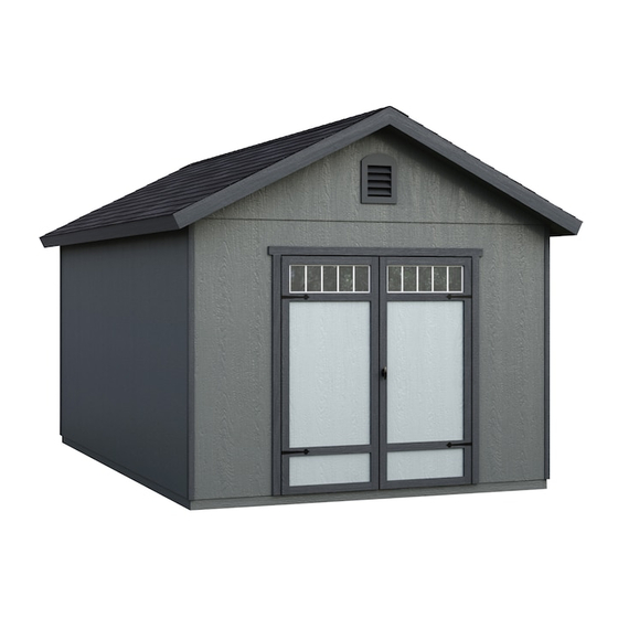
16940 01/03/2018 A Backyard Products Company LYNWOOD GABLE 10' x 8' (305 x 243,8 cm) ACTUAL FLOOR SIZE IS 120 x 96" (304,8 x 2438 cm) KEEP THIS MANUAL FOR FUTURE REFERENCE IMPORTAN T ! READ INSTRUCTIONS THOROUGHLY PRIOR TO BEGINNING ASSEMBLY. - Page 4 TOOLS Required Optional Phillips Tool Belt/ Utility Knife Screwdriver Nail Pouch Shingle Blades Drill / Driver Caulk Gun 1/8" Drill Bit Tin Snips 1/4" Drill Bit (for drip edge) 5/16" Drill Bit Paint Tools 1/2" Drill Bit Chalk Line #2 Philips Drive Bit Safety Glasses Hammer Nail Gun...
-
Page 5: Additional Materials
ADDITIONAL MATERIALS FOUNDATION OR FLOOR MATERIALS • This shed does not include any floor or leveling materials. • See the FLOOR LEVELING section on page 7 for recommended methods and suggested materials to properly level your floor, as this will vary depending on your specific site. WOOD FLOOR FRAME MATERIAL REQUIRED: Use only wood treated for ground contact and fasteners approved for use with treated wood. -
Page 6: Parts List
PARTS IDENTIFICATION AND SIZES Part identification WOOD SIZE CONVERSION CHART letters are stamped on some parts. Nominal Board Size Actual Size 2" x 4"....1-1/2" x 3-1/2" (3,8 x 8,9 cm) 1" x 4"....3/4" x 3-1/2" (1,9 x 8,9 cm) 2" x 3"....1-1/2" x 2-1/2" (3,8 x 6,3 cm) Check these locations for 1"... - Page 7 PARTS LIST continued... 2 x 3 x10-1/8" (5,1 x 7,6 x 25,7 cm) 2 x 4 x 24" (5,1 x 10,2 x 61 cm) 1 x 4 x 23-7/8" (2,5 x 10,2 x 60,6 cm) 1 x 4 x 96" (2,5 x 10,2 x 243,8 cm) 2 x 4 x 96"...
-
Page 8: Fasteners & Hardware
FASTENERS & HARDWARE NAIL BOXES (not included) 3" (7,6 cm) BOXES 2" (5,1 cm) BOXES FASTENER/HARDWARE BAG 1-1/2" (3,8 cm) 1-1/4" (3,2 cm) x165 2" (5,1 cm) 3" (7,6 cm) 1/2" (1,3 cm) 2" (5,0 cm) 1-5/8" (4,1 cm) (NOT ACTUAL SIZE) 3/8"... - Page 9 FLOOR LEVELING OPTIONS There are multiple ways to level your floor frame. Our recommended leveling method is shown below. Leveling materials are not included in this kit. PREFERRED METHOD - 4x4 TREATED RUNNERS • 3" Screws angled into 4x4. • (2) at each point frame •...
- Page 10 CONCRETE FOUNDATION If you choose to install your kit on a concrete slab refer to the diagram below. Treated Sill Plate Caulk between sill plate and concrete. 3-1/2" (8,9 cm) 4" (10,2 cm) Building Size Actual Size 243,8 120" x 96" (304,8 x 243,8 cm) 120"...
-
Page 11: Parts Required
FLOOR FRAME PARTS REQUIRED: 3" (7,6 cm) 2 x 4 x 93" (5,1 x 10,2 x 236,2 cm) 2 x 4 x 120" (5,1 x 10,2 x 304,8 cm) BEGIN Orient parts as shown on fl at surface. Measure and mark. HINT: For easier nailing stand on frame. - Page 12 LEVEL AND SQUARE FLOOR FRAME Before attaching fl oor decking, it is important to level and square the fl oor frame. A level and square fl oor frame is required to correctly construct your shed. BEGIN See page 7 for the preferred fl oor leveling method. Use level and check the frame is level before applying fl oor panels.
- Page 13 FLOOR PANELS PARTS REQUIRED: 2" (5,1 cm) 5/8 x 48 x 96" 3/4" GAUGE (1,6 x 121,9 x 243,8 cm) BLOCK Ensure your floor frame is square by installing one panel and squaring frame. Install panels with rough side up (painted grid lines). BEGIN Attach the 48 x 96"...
- Page 14 FLOOR PANELS PARTS REQUIRED: x100 2" (5,1 cm) 5/8 x 23-7/8 x 96" 3/4" GAUGE 5/8 x 48 x 96" BLOCK (1,6 x 60,6 x 243,8 cm) (1,6 x 122 x 243,8 cm) Continue installing panels fl ush to installed panel and along edges as shown. Use the Gauge Block to maintain the 3/4"...
- Page 15 IMPORTANT! Check that the floor frame is level after installing floor panels. Re-level if needed. • The floor should be used as a stable work surface for wall construction. • Organize your assembly procedure during the build process HINT: to avoid over-handling of the walls. LEFT WALL BACK WALL RIGHT WALL...
-
Page 16: Rafter Assembly
RAFTER ASSEMBLY PARTS REQUIRED: 3" (7,6 cm) 2 x 4 x 4-7/8" (5,1 x 10,2 x 12,4 cm) It is very important to assemble your rafters using the following method for an even and fl at roof. You will build a rafter jig using the fl oor and two CLA parts as shown. ¸... - Page 17 RAFTER ASSEMBLY PARTS REQUIRED: 2" (5,1 cm) 1-5/8" (4,1 cm) GUSSET 6 x 24" (15,2 x 61 cm) 2 x 4 x 75-1/4" (5,1 x 10,2 x 191,1 cm) ¸ BEGIN Place two rafters ECN into the jig as shown. Keep ECN firm against outside CLA's as shown (Fig.A).
- Page 18 RAFTER ASSEMBLY PARTS REQUIRED: 2" (5,1 cm) 1-5/8" (4,1 cm) GUSSET 6 x 24" (15,2 x 61 cm) 2 x 4 x 75-1/4" (5,1 x 10,2 x 191,1 cm) Gable-end rafter assemblies only have one gusset. Repeat steps 1 through 2 to assemble two more rafters with only one gusset. 1/4"...
- Page 19 FRONT WALL (Door Header) PARTS REQUIRED: 3" (7,6 cm) 2 x 4 x 67" (5,1 x 10,2 x 170,2 cm) 7/16 x 3 x 67" (1,1 x 7,6 x 170,2 cm) BEGIN Place (1) AM and OSB end-to-end on fl at surface, fl ush in middle. Center OSB on top of AM.
-
Page 20: Front Wall
FRONT WALL PARTS REQUIRED: 3" (7,6 cm) 2 x 4 x 24-1/2" (5,1 x 10,2 x 62,2 cm) 2 x 4 x 44-1/2" (5,1 x 10,2 x 113 cm) 2 x 4 x 68-1/2" (5,1 x 10,2 x 174 cm) Pre Assembled Header 2 x 4 x 72"... - Page 21 FRONT WALL PARTS REQUIRED: 2" (5,1 cm) 48 x 76" (121,9 x 193 cm) x1 LEFT + x1 RIGHT Place left 48" x 76" panel onto wall frame flush to top as shown. Secure panel with two 2" nails 6" apart. Repeat STEP 3 to attach the right 48"...
- Page 22 FRONT WALL PARTS REQUIRED: 3" (7,6 cm) 2" (5,1 cm) Temporary Support 11-7/8 x 76" 1 x 3 x 72" (1,6 x 7,6 x 182,9 cm) (30,2 x 193 cm) Place 11-7/8" x 76" panels onto wall frame fl ush to top of frame as shown. Secure panels with two 2"...
- Page 23 BACK WALL PARTS REQUIRED: 3" (7,6 cm) 2 x 4 x 72" (5,1 x 10,2 x 182,9 cm) 2 x 4 x 68-1/2" (5,1 x 10,2 x 174 cm) 2 x 4 x 44-1/2" (5,1 x 10,2 x 113 cm) BEGIN Orient parts on edge on floor.
- Page 24 BACK WALL PARTS REQUIRED: 2" (5,1 cm) 48 x 76" 3/4" GAUGE BLOCK (121,9 x 193 cm) Install all panels with primed side up. Place 48" x 76" panel onto frame flush at top and with a 3/4" gap on right side. Maintain 3/4"...
- Page 25 BACK WALL PARTS REQUIRED: 2" (5,1 cm) 48 x 76" 23-7/8 x 76" (121,9 x 193 cm) (60,6 x 193 cm) Place 23-7/8" x 76" panel fl ush with installed 48" x 76" panel edge. Ensure panel is fl ush at top. Secure using 2" nails 6" apart on edges. Place 48"...
-
Page 26: Side Walls
SIDE WALLS PARTS REQUIRED: 3" (7,6 cm) 2 x 4 x 72" (5,1 x 10,2 x 182,9 cm) 2 x 4 x 96" (5,1 x 10,2 x 243,8 cm) YOU WILL BUILD IDENTICAL SIDE WALLS HINT: BEGIN For easier nailing stand on frame. - Page 27 SIDE WALLS PARTS REQUIRED: 2" (5,1 cm) 3/4" GAUGE 48 x 76" BLOCK (121,9 x 193 cm) Install all panels with primed side up. Place 48" x 76" panel onto frame flush at top and with a 3/4" gap on right side. Maintain 3/4"...
- Page 28 SIDE WALLS PARTS REQUIRED: 2" (5,1 cm) 48 x 76" (121,9 x 193 cm) Place 48" x 76" panel fl ush with installed 48" x 76" panel edge. Ensure panel is fl ush at top. Secure using 2" nails 6" apart on edges. For squareness maintain fl ush along panel edges.
-
Page 29: Back Wall Installation
BACK WALL INSTALLATION PARTS REQUIRED: 3" (7,6 cm) 1-1/2 x 2-1/2 x 69" (3,8 x 6,3 x 175,3 cm) 3" (7,6 cm) 2" (5,1 cm) BEGIN Stand back wall on fl oor. Center back wall assembly on the 120" (304,8 cm) fl oor dimension. Use OO as a temporary brace. - Page 30 LEFT WALL INSTALLATION PARTS REQUIRED: 3" (7,6 cm) 1-1/2" (3,8 cm) 2" (5,1 cm) 3" (7,6 cm) 2" (5,1 cm) 2" (3,8 cm) Flush Screw BEGIN STEP FIRST Flush Stand left wall on fl oor. SCREW It is important to secure the gable end wall 2"...
- Page 31 FRONT WALL INSTALLATION PARTS REQUIRED: 1-1/2" (3,8 cm) 2" (5,1 cm) 3" (7,6 cm) BEGIN Stand front wall on fl oor. Center front wall assembly on the 120" (304,8 cm) fl oor dimension. Panel Flush 3" (7,6 cm) Screw STEP FIRST Secure top of front wall using one 2"...
- Page 32 FRONT WALL INSTALLATION PARTS REQUIRED: 3" (7,6 cm) 2" (5,1 cm) Nail lower edge of panels to fl oor frame using 2" nails 6" apart. Angle nail to hit fl oor frame (Fig. D). Secure front wall bottom plates to fl oor using 3" nails (Fig. D). 3"...
- Page 33 RIGHT WALL INSTALLATION PARTS REQUIRED: 2" (5,1 cm) BEGIN Remove temporary supports and stand right wall on fl oor. It is important to secure the right wall in the following order: Beginning at top of front and back walls, secure using one 2" screw into right wall top plate (fi g A). ENSURE TOP OF WALL FRAMES ARE FLUSH.
- Page 34 RIGHT WALL INSTALLATION PARTS REQUIRED: 3" (7,6 cm) 1-1/2" (3,8 cm) 3" (7,6 cm) 2" (5,1 cm) Nail lower edge of panels to fl oor using 2" nails 6" apart. Angle nail to hit fl oor frame (Fig. C). 2" (5,1 cm) Nails 6"...
- Page 35 RAFTERS PARTS REQUIRED: 3" (7,6 cm) Preassembled Rafter Preassembled Rafter (2 gusset) (1 gusset) ¸ BEGIN Secure rafters to top plate with two 3" screws above notch, as shown in Fig. A, B. Note the One Gusset Rafters at each end. 24-3/8"...
- Page 36 DOORS PARTS REQUIRED: 3" (7,6 cm) 1-1/2 x 2-1/2 x 69" (3,8 x 6,3 x 175,3 cm) 1-1/4" (3,2 cm) 1 x 3 x 5" (2,5 x 7,6 x 12,7 cm) Left Door Assembled Right Door Assembled BEGIN Orient parts as shown on flat surface. 3/8"...
- Page 37 DOORS PARTS REQUIRED: 3" (7,6 cm) 1-1/2 x 2-1/2 x 69" (3,8 x 6,3 x 175,3 cm) BEGIN Attach temporary support OO as a ledger board flush under wall panels for doors to rest on, using three 3" screws (Fig. A). Fig.
- Page 38 DOORS PARTS REQUIRED: 2" (5,1 cm) 64" Metal Threshold 19/32 x 3 x 26-5/8" (1,5 x 7,6 x 67,6 cm) 3/4" (1,9 cm) x11 3/4" (1,9 cm) Bagged seperately / special coating 19/32 x 3 x 72" (1,5 x 7,6 x 183 cm) Secure door trim from inside using 3/4"...
- Page 39 DOORS PARTS REQUIRED: 3/4" (1,9 cm) Transom Window From inside of door, apply high quality exterior-grade caulk behind frame near edge before installing to seal window. Inside of door, position window in opening and ensure window is square with door edge. Use four screws to secure each window.
- Page 40 DOOR STIFFENERS PARTS REQUIRED: 2" (5,1 cm) 1-1/2 x 2-1/2 x 69" (3,8 x 6,3 x 175,3 cm) BEGIN Center OO vertically on the left door in the door opening (Fig. A) overlapping 3/4" (1,9 cm) from the edge of door (Fig. B). Secure using (7) 2"...
-
Page 41: Door Hardware
DOOR HARDWARE PARTS REQUIRED: 1/2" (13 mm) Drill Bit 1/4" (6 mm) Drill Bit 3/4" (1,9 cm) BEGIN Measure and mark location of hole on outside of right door as shown (Fig. A) . Pre-drill hole with 1/4" drill. Re-drill hole with 1/2" drill (Fig. A) . Keep drilled hole square to trim to avoid breaking edge of 1-1/2"... - Page 42 DOOR HARDWARE PARTS REQUIRED: 3-Point Door Locking Mechanism Handle (locking) with Screws 1-1/4” 1-1/4” Secure backplate with 1" screws and handle with 1-1/4" screws as shown. 1-1/4" Pan Head Screw Backplate Screw 1-1/4" Wood Screw 1-1/4" Pan Head Screw Pre drill for screws...
-
Page 43: Lower Bracket
DOOR HARDWARE See following pages for mounting locations of brackets and plates. Plate Washer 1-1/4" Pan Head Screw UPPER BRACKET 3/4" Tech Screw (with offset) Orient bracket as shown. Washer 3/4" Tech Screw Washer LOWER BRACKET (with offset) Orient bracket as shown. 1-1/4"... -
Page 44: Right Door
DOOR HARDWARE TOP of Door 2-1/4" IMPORTANT! This rod to edge of door RIGHT DOOR LEFT DOOR Make sure rods are straight up and down when locating brackets. 2-1/4" BOTTOM of Door... - Page 45 DOOR HARDWARE Drill with 3/8" bit PLATE to 2" depth. FRAMING Align Plates with vertical rod points. Drill-thru with 3/8" drill bit to 2" depth into header and floor. VERTICAL RODS FLOOR PLATE...
-
Page 46: Top Plate
FRONT GABLE PANELS PARTS REQUIRED: 1-1/2" (3,8 cm) 2 x 3 x 23-1/2" (5,1 x 10,2 x 59,7 cm) BEGIN Measure distance from over-door trim to top plate (Fig. A). Fig. A TOP PLATE Orient UV on fl at as shown. Transfer the measurement from Fig. - Page 47 FRONT GABLE PANELS PARTS REQUIRED: Place gable center panel (use panel with vent hole) fl ush to installed left panel. Secure panel to UV using 1-1/2" nails. Place second UV as shown under center panel as shown. Transfer the measurement from STEP - 1, Fig. A onto the left front gable panel. Secure panel to UV using 1-1/2"...
- Page 48 FRONT GABLE PARTS REQUIRED: 3" (7,6 cm) 2" (5,1 cm) Front Gable Unit BEGIN Set front gable unit on top plate, centered on wall, resting on 2 x 4 gable supports UV and over-door trim (Fig. A). Hold gable secure with one 2" nail on each side as shown. BE SURE GABLE IS CENTERED ON WALL BEFORE NAILING.
- Page 49 BACK GABLE PANELS PARTS REQUIRED: 1-1/2" (3,8 cm) 2 x 3 x 23-1/2" (5,1 x 10,2 x 59,7 cm) BEGIN Orient UV on fl at as shown. Place left front gable panel as shown and secure using 1-1/2" nails. UV (on fl at) 1-1/2"...
- Page 50 BACK GABLE PARTS REQUIRED: 3" (7,6 cm) 2" (5,1 cm) Back Gable Unit BEGIN Set back gable unit on top plate, centered on wall, resting on 2 x 4 gable supports UV and over-door trim (Fig. A). Hold gable secure with one 2" nail on each side as shown. BE SURE GABLE IS CENTERED ON WALL BEFORE NAILING.
- Page 51 FRONT GABLE OVERHANG PARTS REQUIRED: 2" (5,1 cm) 3" (7,6 cm) 2 x 4 x 4-7/8" (5,1 x 10,2 x 12,4 cm) 7/16 x 9 x 27-1/4" 7/16 x 9 x 48" (1,1 x 20 x 69,2 cm) (1,1 x 20 x 121,9 cm) 2 x 3 x 75-1/4"...
- Page 52 FRONT GABLE OVERHANG PARTS REQUIRED: 3" (7,6 cm) 2" (5,1 cm) BEGIN Place the left gable unit onto rafter as shown (Fig. A). Ensure gable unit is fl ush against gable panel, fl ush at peak (Fig. B). Secure gable unit panel to rafter using 2" nails 6" apart (Fig. A). Flush 2"...
- Page 53 ROOF PANELS PARTS REQUIRED: x118 2" (5,1 cm) 3/4" GAUGE BLOCK 7/16 x 27-1/4 x 48" 7/16 x 48 x 96" (1,1 x 69,2 x 121,9 cm) (1,1 x 121,9 x 243,8 cm) Roof panels may cause serious injury until securely fastened. Note: all roof panels need to be installed with the rough side up (painted grid lines).
- Page 54 ROOF PANELS PARTS REQUIRED: Attach another 27-1/4" x 48" roof panel fl ush to the installed panels. Secure panel with two 2" nails in the corners. Flush Flush Two Nails Secure the roof panels using 2" nails 6" apart on edges and 12" apart inside panel. 6"...
- Page 55 FRONT GABLE SOFFITS PARTS REQUIRED: 2" (5,1 cm) 3/8 x 7-7/8 x 73-5/16" (1 x 20 x 186,2 cm) Ensure soffi t boards are fl ush at peak and to each other (Fig. B, Fig. D). BEGIN Position 73-5/16" overhang board Primed Side Down fl ush to front wall (Fig A) and to center of gable assembly (Fig B).
- Page 56 EAVE SIDE SOFFITS PARTS REQUIRED: 2" (5,1 cm) 3/8 x 5-7/8 x 24-3/4" (1 x 14,9 x 62,9 cm) 3/8 x 5-7/8 x 72-3/4" (1 x 14,9 x 184,8 cm) Ensure soffi t boards are fl ush at rafter ends (Fig. B) and fl ush at seam. BEGIN Position 72-3/4"...
- Page 57 EAVE SIDE FASCIA PARTS REQUIRED: 2" (5,1 cm) 3/8 x 4-7/8 x 24-3/4" (1 x 12,1 x 62,9 cm) 3/8 x 4-3/4 x 80-5/8" (1 x 12,1 x 204,8 cm) BEGIN Position 4-3/4" x 80-5/8" fascia board with primed side out, fl ush with roof panels (Fig. A) and fl ush with front gable fascia as shown.
- Page 58 GABLE FASCIA PARTS REQUIRED: SHIM 2" (5,1 cm) 3/8 x 3-1/4 x 5-7/8" (1,0 x 8,3 x 14,9 cm) Painted 3/8 x 4-3/4 x 75-7/8" (1 x 12,1 x 192,7 cm) Painted Green 3/8 x 4-3/4 x 75-7/8" (1 x 12,1 x 192,7 cm) BEGIN Position 3-1/4 x 5-7/8"...
- Page 59 CORNER TRIM PARTS REQUIRED: 2" (5,1 cm) 3/8 x 1-3/4 x 73-7/8" (1,0 x 4,4 x 187,6 cm) 3/8 x 1-3/4 x 74-1/2" (1,0 x 4,4 x 189,2 cm) ¸ BEGIN Attach one 73-7/8" trim board fl ush under soffi t panel and against eave wall (Fig. A, B) using one 2"...
- Page 60 SHELVING PARTS REQUIRED: 2" (5,1 cm) 2 x 3 x10-1/8" (5,1 x 7,6 x 25,7 cm) 3/8 x 8 x 12-1/2" (1 x 20,3 x 31,8 cm) BEGIN Secure AE to bracket panels using three 2" nails. Assemble 6 shelf supports as shown; 5 right-side, 1 left-side. Flush 2"...
- Page 61 SHELVING PARTS REQUIRED: 2" (5,1 cm) 1-1/4" (3,2 cm) 7/16 x 11-7/8 x 96" (1,1 x 30,2 x 243,8 cm) 7/16 x 11-7/8 x 23-7/8" (1,1 x 30,2 x 60,6 cm) 1 x 4 x 96" (2,5 x 10,2 x 243,8 cm) 1 x 4 x 23-7/8"...
- Page 62 LOFT PARTS REQUIRED: 3" (7,6 cm) 2 x 4 x 24" (5,1 x 10,2 x 61 cm) 2 x 4 x 96" (5,1 x 10,2 x 243,8 cm) ¸ BEGIN Orient parts TP and RL on a flat surface. Spread glue across RL and TP as shown (Fig. A). Hold parts TP and RL flush and aligned.
- Page 63 LOFT PARTS REQUIRED: 3" (7,6 cm) 2 x 4 x 24" (5,1 x 10,2 x 61 cm) (NOT ACTUAL SIZE) 3/8" x5-1/2" (1 cm x 14 cm) Hex Bolt 3/8" (1 cm) 2 x 4 x 96" (5,1 x 10,2 x 243,8 cm) Flat Washer Pre-Assembled Loft Joist 3/8"...
- Page 64 LOFT PARTS REQUIRED: 2" (5,1 cm) 23-7/8" x 96" (60,6 x 243,8 cm) Install loft panel centered over loft joists. Secure with 2" nails 8" apart. There will be a gap of approximately 8-1/2" on either side. 2" (5,1 cm) 8 "...
- Page 65 COLLAR TIE PARTS REQUIRED: 2" (5,1 cm) 1 x 3 x 72" (2,5 x 7,6 x 182,9 cm) BEGIN Position and level collar tie on 3rd rafter from loft. HINT: For best appearance install collar tie on rafter facing away from door opening. Attach with 2"...
- Page 66 GABLE VENT PARTS REQUIRED: #8 x 1" (2,5 cm) Pan Head Screws #15021 ¸ BEGIN Locate vent in the gable wall as shown. Secure using 1" screws. #8 x 1" (2,5 cm) Pan Head Screws FINISH You have fi nished installing your gable vent.
- Page 67 WALL VENT PARTS REQUIRED: 1/2" (1,3 cm) 8 x 16" (20,3 x 35,6 cm) BEGIN Choose a wall for vent location (A lower location is best if you have a gable vent). Measure and mark vent hole in wall as shown. Cut out marked opening. Caulk behind vent fl anges.
- Page 68 PAINT & CAULK - NOT INCLUDED - • Use acrylic latex caulk that is paintable. Caulk at all horizontal and vertical seams, between the trim and walls, and all around the door trim. • Use a high quality exterior acrylic latex paint. When painting your building, there are a few key areas that can be easily overlooked that must be painted: •...
- Page 69 SHINGLES - NOT INCLUDED - • Follow directions provided by manufacturer and these instructions. Familiarize yourself with a 3-Tab Shingle. Notch Notch SHINGLE NAIL PATTERN 1/2" 1" Sealing Strip 1" (1,3 cm) (2,5 cm) (2,5 cm) Half A Rain Slot Full Rain Slot NAILS NEVER DRIVE FASTENERS INTO OR ABOVE SEALING STRIPS.
- Page 70 SHINGLES continued... Beginning at front of shed, install first row of shingles with notch at 1" past roof edge or flush with drip edge. Roof Deck FRONT OF BACK OF SHED SHED 1" (2,5 cm) Flush with starter row. Notch - or - Drip Edge Flush with starter row.
- Page 71 SHINGLES continued... Continue installing rows of shingles to the peak. At the peak make sure there is a maximum of 5" or less to the rain slot, as shown below. If shingles overlap at ridge cut to peak with a utility knife. 5"...
- Page 72 SHINGLES - RIDGE CAP • You will finish off the top of the roof with a ridge cap made from shingles. BEGIN Cut shingles into THREE pieces. Hint: Use cut-off pieces first. 2" 2" (5 cm) (5 cm 2" 2" 2"...
- Page 73 SHINGLES - RIDGE CAP continued... Continue installing ridge cap to back of roof. Make sure there is 4" between the shingle-color and edge of shingles. 4" (10 cm) Trim cap off fl ush to shingles When you have 4" minimum of shingle color cut one piece to cap your roof. Cut at top of rain slot.
- Page 74 WARRANTY REGISTRATION Please complete your warranty registration to properly validate your warranty. Register your product online at: www.OnlineWarranty.net LIMITED CONDITIONAL WARRANTY* Backyard Storage Solutions, LLC warrants the following: Every product is warranted from defects in workmanship and manufacturing for 1 year. All accessories, hardware and metal components are warranted for 2 years.
Need help?
Do you have a question about the LYNWOOD GABLE and is the answer not in the manual?
Questions and answers