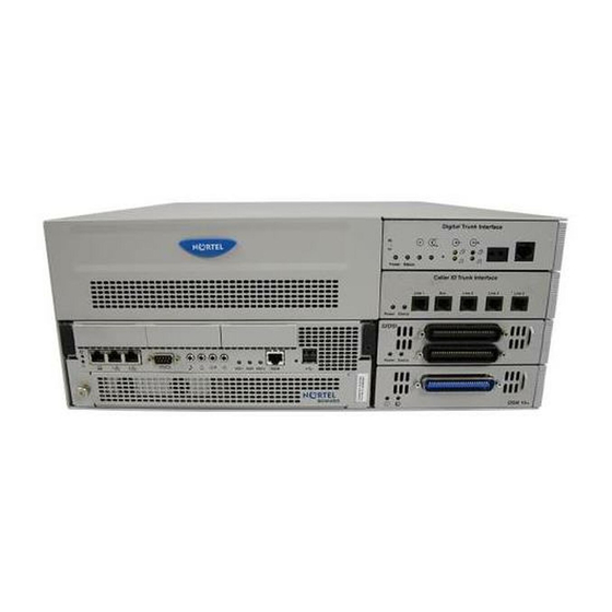
Nortel BCM450 Maintenance Manual
Business communications manager
Hide thumbs
Also See for BCM450:
- Feature user manual (21 pages) ,
- Troubleshooting manual (102 pages) ,
- Installation manual (142 pages)

Related Manuals for Nortel BCM450


Summary of Contents for Nortel BCM450
- Page 1 Nortel Business Communications Manager 450 Maintenance Release: 5.0 Document Revision: 02.03 NN40170-503...
- Page 2 Language type: English Copyright © 2009 Nortel Networks All Rights Reserved. NORTEL, the globemark design, and the NORTEL corporate logo are trademarks of Nortel Networks. Maxell is a trademark of Hitachi Maxell, Ltd. All other trademarks are the property of their respective owners.
-
Page 3: Table Of Contents
Contents New in this release Features 5 Introduction System maintenance BCM450 equipment replacement BCM450 internal component replacement Replacing a media bay module 15 Prerequisites 15 Procedure steps 15 Removing the power supply 16 Connecting the new power supply 17 Removing the hard disk 17... - Page 4 Prerequisites 39 Procedure steps 39 Reinstalling the BCM450 base function tray 40 Prerequisites 40 Procedure steps 40 Removing the BCM450 main unit top cover 40 Prerequisites 41 Procedure steps 41 Installing the main unit top cover 42 Prerequisites 42 Procedure steps 42...
-
Page 5: New In This Release
5)” Features • BCM450 5.0 supports RAID for disk mirroring. This allows you to maintain a redundant image of your hard drive to maintain service in the event of a hard disk failure. For more information, see Removing the hard disk... - Page 6 6 New in this release Business Communications Manager 450 Maintenance NN40170-503 02.04 Standard August 2009 Copyright © 2009 Nortel Networks...
-
Page 7: Introduction
Manager BCM systems. Navigation • System maintenance (page 9) • BCM450 equipment replacement (page 11) • BCM450 internal component replacement (page 13) • Redundant power supply installation (page 25) • BCM modules management (page 45) • Common procedures (page 35) •... - Page 8 8 Introduction Business Communications Manager 450 Maintenance NN40170-503 02.04 Standard August 2009 Copyright © 2009 Nortel Networks...
-
Page 9: System Maintenance
Prerequisites to system maintenance • Ensure your BCM system is properly installed. For more information about installing a BCM system, see Nortel Business Communications Manager 450 5.0 Installation — System (NN40170-303). System maintenance tasks This work flow shows you the sequence of tasks you perform to maintain your BCM system. - Page 10 10 System maintenance Figure 1 System maintenance tasks System maintenance navigation • BCM450 equipment replacement (page 11) • BCM modules management (page 45) Business Communications Manager 450 Maintenance NN40170-503 02.04 Standard August 2009 Copyright © 2009 Nortel Networks...
-
Page 11: Bcm450 Equipment Replacement
Equipment replacement tasks This work flow shows you the sequence of tasks you perform to replace equipment for your BCM450 system. To link to any tasks, click on Equipment replacement navigation (page 12). - Page 12 12 BCM450 equipment replacement Figure 2 Equipment replacement tasks Equipment replacement navigation • BCM450 internal component replacement (page 13) Business Communications Manager 450 Maintenance NN40170-503 02.04 Standard August 2009 Copyright © 2009 Nortel Networks...
-
Page 13: Bcm450 Internal Component Replacement
BCM450 internal component replacement You can replace components in the BCM450 main unit if they are defective or damaged. Prerequisites to BCM450 internal component replacement • Ensure the BCM450 system is shut down. For more information, see Shutting down the system for maintenance (page 36). - Page 14 14 BCM450 internal component replacement BCM450 internal component replacement procedures This task flow shows you the sequence of procedures you perform to replace an internal component in a BCM450 main unit. To link to any procedure, click BCM450 internal component replacement navigation (page 14).
-
Page 15: Replacing A Media Bay Module
This section describes how to replace a media bay module (MBM) installed in your BCM450 main unit or expansion cabinet if it is defective or damaged. This section describes replacing an MBM with the same type of MBM. If you want to replace an MBM with a different type of MBM, you must treat it as a new installation. -
Page 16: Removing The Power Supply
16 BCM450 internal component replacement Removing the power supply Remove the defective power supply from your BCM450 main unit or BCM450 expansion cabinet before installing the new power supply. WARNING Risk of leakage currents You must disconnect the telephony and data networking cables from the system before disconnecting the power cord from a grounded outlet. -
Page 17: Connecting The New Power Supply
HDD LED and is not listed in the Status section will be the failed disk to be replaced. Turn off the BCM450 system and disconnect it from the AC power source. For more information, see... -
Page 18: Installing The Hard Disk
Lift the hard disk from the hard disk bracket, and set it on a flat, clean, static- free surface. --End-- Installing the hard disk Install the new hard disk into the BCM450 main unit. Prerequisites • Remove the hard disk. For more information about removing the hard disk, “Removing the hard disk (page... -
Page 19: Installing The Cec
Turn off the BCM450 system. For more information, see “Shutting down the system for maintenance (page 36)”. • Ensure the BCM450 main unit is disconnected from the AC power source. Business Communications Manager 450 Maintenance NN40170-503 02.04 Standard August 2009... - Page 20 Procedure steps Step Action Turn off the BCM450 system, and remove the base function tray. Attach one end of a grounding strap to your wrist and the other end to a grounded metal surface. Remove the plastic cap on the CEC slot on the front of the base function tray.
-
Page 21: Replacing Memory
BCM450 internal component replacement 21 --End-- Replacing memory Use the following procedure to replace the random access memory card in the BCM450 main unit if it is defective or damaged. Prerequisites • Ensure that you have available a replacement DDR RAM card (up to 1gigabyte, 533 megahertz). -
Page 22: Removing The Cooling Fan
Shutting down the system for maintenance (page 36). • Ensure the BCM450 main unit is disconnected from the AC power source. Procedure steps Step Action Attach one end of a grounding strap to your wrist and the other end to a grounded metal surface. -
Page 23: Replacing The Clock/Calendar Battery
Attention: Ensure the label of the new fan faces the back of the BCM450 unit. Air must flow out of the unit as indicated by the embossed arrows on the fan. -
Page 24: Prerequisites
Attention: You must replace the battery with a CR2032, 3 Volt Maxell coin cell battery. The use of any other manufacturer can invalidate the safety approval of the BCM450 main unit and possibly cause a fire or explosion. Prerequisites •... -
Page 25: Redundant Power Supply Installation
The following task flow shows you the sequence of procedures you perform the sequence of tasks you perform to install a redundant power supply and cooling fan in your BCM450 system. To link to any procedure, select Redundant power supply installation navigation (page 26). -
Page 26: Redundant Power Supply Installation Navigation
• Turn off the BCM450 system. • You require a Phillips head screwdriver. • Ensure you disconnect the BCM450 main unit from the AC power source. Business Communications Manager 450 Maintenance NN40170-503 02.04 Standard August 2009 Copyright © 2009 Nortel Networks... -
Page 27: Procedure Steps
Step Action Turn off the BCM450 system. Disconnect the BCM450 system from the AC power outlet. Attach one end of a grounding strap to your wrist and the other end to a grounded metal surface. Remove the main unit top cover. -
Page 28: Installing The Redundant Power Supply Cage
Turn off the BCM450 system. • You require a Phillips head screwdriver. • Ensure you disconnect the BCM450 main unit from the AC power source. • Remove the standard power supply from the main unit. For more information, see Removing the power supply (page 16) - Page 29 +12 V power cable (P9), the 3.3 V load cable (PB), and the PS monitor cable (PA) to the tie-wrap. Secure the cables to the power supply support bracket with the tie-wrap. Business Communications Manager 450 Maintenance NN40170-503 02.04 Standard August 2009 Copyright © 2009 Nortel Networks...
- Page 30 30 Redundant power supply installation Install the power supply support bracket in the BCM450 main unit. Position the redundant power supply cage in the main unit. Ensure the power supply module tray opening faces the rear of the main unit.
-
Page 31: Installing The Secondary Cooling Fan
Turn off the BCM450 system. • You require a Phillips head screwdriver. • Ensure you disconnect the BCM450 main unit from the AC power source. CAUTION Risk of damage to equipment You must wear an antistatic grounding strap at all times when handling electronic components. -
Page 32: Procedure Steps
Ensure you orient the fan cable to the bottom of the fan and that the fan label is closest to the grill on the panel. Attention: Ensure the label of the new fan faces the back of the BCM450 unit. Air must flow out of the unit as indicated by the embossed arrows on the fan. -
Page 33: Installing The Power Supply Modules
Redundant power supply installation 33 Connect the fan cable connector of the leftmost fan (when looking at the back of the BCM450) to the Fan 1 connector on the CIF card. Fan 1 Fan 2 Connect the second fan cable connector to the Fan 2 connector on the CIF card. -
Page 34: Procedure Steps
Connect both AC power cords to AC outlets. If only one cord is connected, only the connected power supply functions. Turn on the BCM450 system. Ensure both power status lights are on, and that the fans are functioning properly. --End--... -
Page 35: Common Procedures
Removing the BCM450 main unit top cover (page 40) • Installing the main unit top cover (page 42) Disconnecting the cables from the main unit Disconnect the cables from the BCM450 main unit to prepare the system for maintenance operations. WARNING Risk of leakage currents... -
Page 36: Disconnecting The Cables From The Expansion Cabinet
USB port. Remove the power supply cord from the main unit. --End-- Disconnecting the cables from the expansion cabinet Disconnect the cables from the BCM450 expansion cabinet to prepare the system for maintenance operations. Prerequisites • Use Element Manager to disable the media bay modules (MBM) that are installed in the expansion cabinet. - Page 37 Common procedures 37 Prerequisites • Ensure you have a recent backup of the BCM450 system programming. If a recent backup is not available, use Element Manager to back up the system data. For information about backing up the system data, see Nortel Business Communications Manager Administration and Security.
-
Page 38: Returning The System To Operation
Procedure steps Step Action If you removed the BCM450 main unit from the rack or wall, replace it. Ensure your BCM450 power supply is connected to your BCM450 system and to an AC wall outlet or a UPS. Ensure the telephony cables are connected to the BCM main unit and BCM expansion cabinets. -
Page 39: Removing The Bcm450 Base Function Tray
Communications Manager 450 Administration and Security. --End-- Removing the BCM450 base function tray Remove the BCM450 base function tray from the system if it is defective or if you need to perform maintenance on it. Prerequisites • You must shut down the BCM450 system. For more information, see Shutting down the system for maintenance (page 36). -
Page 40: Reinstalling The Bcm450 Base Function Tray
Observe the system status monitor LEDs to ensure the base function tray initializes correctly. --End-- Removing the BCM450 main unit top cover Use this procedure to remove the top cover of the BCM450 main unit if you want to perform maintenance activities. Business Communications Manager 450 Maintenance NN40170-503 02.04 Standard... -
Page 41: Prerequisites
Common procedures 41 Attention: Do not operate the BCM450 main unit with the top cover removed. Do not leave the top cover removed for extended periods of time. Prerequisites • Ensure the BCM450 main unit is disconnected from the AC power source. -
Page 42: Installing The Main Unit Top Cover
Attach one end of the grounding strap to your wrist and the other end to a grounded metal surface. Set the top cover on the main unit. Business Communications Manager 450 Maintenance NN40170-503 02.04 Standard August 2009 Copyright © 2009 Nortel Networks... - Page 43 Press the top cover down until it rests on the chassis. Install the two top cover screws at the rear of the main unit. --End-- Figure 8 Installing main unit top cover Business Communications Manager 450 Maintenance NN40170-503 02.04 Standard August 2009 Copyright © 2009 Nortel Networks...
- Page 44 44 Common procedures Business Communications Manager 450 Maintenance NN40170-503 02.04 Standard August 2009 Copyright © 2009 Nortel Networks...
-
Page 45: Bcm Modules Management
Launch Element Manager and connect to your BCM450 system. BCM modules management procedures This task flow shows you the sequence of procedures you perform to manage modules in your BCM450 system. To link to any procedure, click on modules management navigation. -
Page 46: Disabling Or Enabling A Bus Or Module
Disabling or enabling a bus or module (page 46) • Disabling or enabling a port channel setting (page 47) • Configuring a Station Module type BCM450 MBM (page 47) • Deconfiguring a Station Module type BCM450 MBM (page 48) •... -
Page 47: Disabling Or Enabling A Port Channel Setting
The State box indicates the mode of operation for the port. If the port is enabled, this box shows “unequipped” unless a device is physically connected. --End-- Configuring a Station Module type BCM450 MBM You can configure BCM450 MBMs through Element Manager. Business Communications Manager 450 Maintenance NN40170-503 02.04 Standard August 2009... -
Page 48: Deconfiguring A Station Module Type Bcm450 Mbm
48 BCM modules management Prerequisites • The BCM450 MBM must be installed in the system. For information about replacing a BCM450 MBM, see Replacing a media bay module (page 15). For information on installing a new BCM450 MBM, see Nortel Business Communications Manager 450 Installation —... -
Page 49: Configuring A Trunk Module Or Combination Mbm
Configuring a Trunk Module or Combination MBM You can configure BCM450 MBMs through Element Manager. Prerequisites • The BCM450 MBM must be installed in the system. For information about replacing a BCM450 MBM, see Replacing a media bay module (page 15). - Page 50 50 BCM modules management Select the module you want to deconfigure. Click Deconfigure. Click OK to delete the configuration for the MBM. --End-- Business Communications Manager 450 Maintenance NN40170-503 02.04 Standard August 2009 Copyright © 2009 Nortel Networks...
-
Page 51: System Leds Reference
System status monitor LEDs The BCM450 system status LEDs on the main unit provide information about the status of the BCM450 system. Use these LEDs to determine if the system is functioning properly and if the system generates an alarm. -
Page 52: Hard Disk Drive Leds On Bcm450
Start-up Profile successfully applied. Blink Yellow Blink Red Start-up Profile failure. Hard disk drive LEDs on BCM450 The following table describes the possible LED states for the hard disk drive LEDs on the BCM450. Table 2 HDD LED states Business Communications Manager 450 Maintenance NN40170-503 02.04 Standard... -
Page 53: Business Communications Manager
Normal operation HDD fault Orange/Flashing Activity Orange RAID Description RAID not enabled Green RAID is operating, HDDs are synchronized. RAID failure. Orange/Flashing Synchronization in progress. Orange Business Communications Manager 450 Maintenance NN40170-503 02.04 Standard August 2009 Copyright © 2009 Nortel Networks... - Page 54 54 System LEDs reference Business Communications Manager 450 Maintenance NN40170-503 02.04 Standard August 2009 Copyright © 2009 Nortel Networks...
- Page 56 Business Communications Manager 450 Maintenance Copyright © 2009 Nortel Networks. Sourced in Canada, the United States, and the United Kingdom. All Rights Reserved. Publication: NN40170-503 Document status: Standard Document issue: 02.04 Document date: August 2009 Product release: BCM 5.0 Job function: Maintenance...
Need help?
Do you have a question about the BCM450 and is the answer not in the manual?
Questions and answers