Advertisement
INSTALLATION
INSTRUCTIONS
Option A
– Regular Arm Installation
SPEED ADJUSTING VALVES
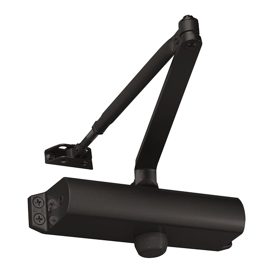
MAIN ARM
DOOR CLOSER
FOREARM
(Right Hand Door)
SPEED ADJUSTING VALVES
MAIN ARM
ARM SHOE
DOOR CLOSER
(Left Hand Door)
Option B
– Top Jamb Installation
MAIN ARM
DOOR CLOSER
FOREARM
ARM SHOE
SPEED ADJUSTING VALVES
DOOR CLOSER
FOREARM
ARM SHOE
SPEED ADJUSTING VALVES
(Right Hand Door)
80-9316-8007-000
REV-1(3/17)
ARM SHOE
FOREARM
(Left Hand Door)
MAIN ARM
1
-1/4
3/4
(32)
(19)
A
Hinge or Pivot
Option A instructions: 1.
screw hole center locations. Mark four (4) hole locations on door for door closer
and two (2) hole locations on frame for arm shoe.
and frame, drill 7/32"(5.5mm) diameter holes for wood screws or drill and tap
#7(.201" diameter) for 1/4-20 machine screws.
shoe to frame using screws (a) or (b).
(c) or (d). SPEED ADJUSTING VALVES MUST BE POSITIONED TOWARD
5.
HINGE SIDE.
Install main arm to top pinion shaft, perpendicular to door,
Secure tightly with arm screw/washer (e).
perpendicular to frame when assembled to preloaded main arm. Secure forearm
to main arm with screw/washer (f).
8.
reference.
Snap pinion cap over shaft at bottom of closer or install (optional)
cover with small screw (j).
Hinge or Pivot
A
3/4
1/2
(19)
(13)
Option B instructions: 1.
screw hole center locations. Mark four (4) hole locations on door for door closer
and two (2) hole locations on frame for arm shoe.
and frame, drill 7/32"(5.5mm) diameter holes for wood screws or drill and tap
#7(.201" diameter) for 1/4-20 machine screws.
shoe to door using screws (a) or (b).
(c) or (d). SPEED ADJUSTING VALVES MUST BE POSITIONED TOWARD
5.
HINGE SIDE.
Install main arm to bottom pinion shaft, perpendicular to door,
Secure tightly with arm screw/washer (e).
perpendicular to door when assembled to preloaded main arm. Secure forearm
to main arm with screw/washer (f).
8.
reference.
Snap pinion cap over shaft at bottom of closer or install (optional)
cover with small screw (j).
YDC201
YDC204
Diagram for Option A
1
6
-3/4
(44.4)
(152)
9
-1/16
(230)
Door Opening
to 100°
101°to 120°
121°to 180°
Using the measurements from diagram A, mark
2.
Drill pilot holes in door
3.
Install adjustable forearm/arm
4.
Mount closer on door using screws
6.
Adjust length of forearm so it is
7.
Adjust closing speed, see page2 for
Diagram for Option B
Door Opening
to 100°
101°to 120°
121°to 180°
9
-1/16
(230)
6
(152)
Using the measurements from diagram B, mark
2.
Drill pilot holes in door
3.
Install adjustable forearm/arm
4.
Mount closer on frame using screws
6.
Adjust length of forearm so it is
7.
Adjust closing speed, see page2 for
7/8
(22)
Inches (mm)
Dim. A
7
(178)
6
(152)
3-1/2
(89)
Inches (mm)
Dim. A
7
(178)
6
(152)
3-1/2
(89)
1
-1/2
(38)
1
-3/4
(44.4)
1
Advertisement
Table of Contents

Related Manuals for Yale YDC201


Summary of Contents for Yale YDC201
- Page 1 INSTALLATION YDC201 INSTRUCTIONS YDC204 Option A – Regular Arm Installation Diagram for Option A -3/4 SPEED ADJUSTING VALVES (22) -1/4 (44.4) (152) MAIN ARM (32) (19) ARM SHOE -1/16 (230) Inches (mm) DOOR CLOSER Door Opening Dim. A to 100°...
- Page 2 Yale Locks & Hardware Product Support Tel 800.438.1951 • www.yalelocks.com Yale Locks & Hardware Is a division of Yale Security Inc., an ASSA ABLOY Group company. 80-9316-8007-000 ReV-1(3/17)
Need help?
Do you have a question about the YDC201 and is the answer not in the manual?
Questions and answers