Advertisement
Quick Links
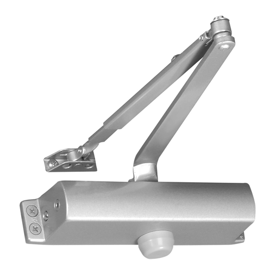
YMDC1101 Installation Instructions
PARALLEL ARM INSTALLATION
CLOSER MOUNTED ON PUSH SIDE OF DOOR
Parallel arm installation for 180° maximum opening.
2-7/8
(73)
3/4
(19)
B
C L Hinge
2-3/4
C
(70)
3/8
2"
3/8
(9)
(50)
(9)
3/4
(19)
4 holes for #14
wood screws
or 1/4-20UNC
machine screws
For Opening To 120°
For Opening 120° - 180°
B
C
7" (176)
8-5/8" (219)
6-1/2" (164)
Spring Tension - Door Size Chart
Maximum Door Width
Full Turns
of Spring
Exterior Door Size
Adjustment
Interior
Screw
Door Size
Swing Out
5 Pounds Opening Force
0
5
36" (914)
32" (813)
10
42" (1067)
36" (914)
12
48" (1219)
42" (1067)
POSITION OF ARMS AND INDEX SETTINGS
Main Arm
Locknut
Index Mark
Forearm
Left hand door, use index mark 3
ILLUSTRATION "A"
Spring Power
Speed Regulating Valves
Adjustment Screw
Away From Hinge Edge
Backcheck
of Door
Adjustment Valve
9-1/16
(230)
Arm Screw and
Lockwasher
Parallel Bracket
B
C
7-1/8" (181)
Swing In
28" (711)
32" (813)
36" (914)
Main Arm
Locknut
Index Mark
Forearm
Right hand door, use index mark 2
ILLUSTRATION "B"
LEFT HAND DOOR SHOWN.
Same dimensions apply for Right Hand
door measured from hinge edge.
Do not scale drawing.
All dimensions given in inches (mm).
4 holes for #14
wood screws
or 1/4-20UNC
machine screws
PARALLEL ARM INSTALLATION INSTRUCTIONS
1. Select degree of opening and use dimensions shown in above
template to mark (4) four holes on door for closer and (2) two
holes on frame for parallel bracket.
2. Drill pilot holes in door and frame for #14 wood screws or drill
and tap for 1/4-20UNC machine screws.
3. Mount closer on door with SPEED REGULATING SCREW
AWAY FROM HINGE EDGE.
4. Attach parallel bracket to door stop as illustrated.
5. Using a wrench on the square shaft on bottom of closer, rotate
shaft approximately 45° toward hinge edge of door. Hold and
place main arm on shaft on top of closer at proper index mark
as illustrated.
FOR LEFT HAND DOOR NO. 3 (ILLUSTRATION "A").
FOR RIGHT HAND DOOR NO. 2 (ILLUSTRATION "B").
Tighten arm screw with lockwasher securely.
6. Remove the arm shoe from the forearm (arm shoe is not used
in this application) and place forearm on parallel bracket stud
and tighten screw securely.
7. Adjust length of forearm so when it is attached to main arm, the
main arm will be slightly away from parallel with closed door,
and assemble at elbow then tighten locknut.
ADJUSTMENT INSTRUCTIONS
CLOSING POWER- As per "Spring Tension Chart" select the correct
number of turns for spring adjustment screw that corresponds with the
installation. Using 5/32" (4mm) allen key, turn adjustment screw full
360° clockwise turns to desired setting.
SPEED- Door closing and latching speeds are controlled by "1", "2"
speed regulating screw separately.
A: Clockwise turns slow the speed. B: Counterclockwise turns increase
the speed.
Closing Speed
Regulating Screw
Latching Speed
Regulating Screw
BACKCHECK ADJUSTMENT- is controlled by the adjustment valve. To
increase Backcheck action, turn valve CLOCKWISE. To decrease or to
turn off Backcheck action, turn valve COUNTERCLOCKWISE.
Parallel
Bracket
Stud
Shaft
Pinion
Cap
Slow
Fast
B
A
Speed
Latch
Advertisement

Related Manuals for Yale YM Series


Summary of Contents for Yale YM Series
- Page 1 YMDC1101 Installation Instructions PARALLEL ARM INSTALLATION CLOSER MOUNTED ON PUSH SIDE OF DOOR Parallel arm installation for 180° maximum opening. LEFT HAND DOOR SHOWN. Parallel Same dimensions apply for Right Hand Bracket door measured from hinge edge. Do not scale drawing. Stud All dimensions given in inches (mm).
- Page 2 100 Yale Avenue, Lenoir City, TN 37771 • Product Support Tel 800.438.1951 • Fax 800.338.0965 • www.yalecommercial.com Yale® is a registered trademark of the respective ASSA ABLOY Group company. Other products' brand names may be trademarks or registered trademarks of their respective owners and are mentioned for reference purposes only.
Need help?
Do you have a question about the YM Series and is the answer not in the manual?
Questions and answers