Table of Contents
Advertisement
Quick Links
Advertisement
Table of Contents

Subscribe to Our Youtube Channel
Related Manuals for Monoprice Blackbird 39670


Summary of Contents for Monoprice Blackbird 39670
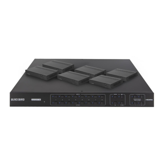
- Page 1 Blackbird™ 4K 8x8 HDBaseT™ Matrix with 6 Receivers P/N 39670 User's Manual...
-
Page 2: Table Of Contents
CONTENTS SAFETY WARNINGS AND GUIDELINES ........................... 4 INTRODUCTION ......................................5 FEATURES ........................................6 CUSTOMER SERVICE ....................................6 PACKAGE CONTENTS .................................... 7 PRODUCT OVERVIEW ................................... 8 Matrix Front Panel ............................................8 Matrix Rear Panel ............................................... 9 Receiver ..................................................10 IR Remote Control ............................................12 SAMPLE CONNECTION DIAGRAM ............................ - Page 3 Interface Tab ............................................... 30 Network Tab ................................................. 31 Access Tab ................................................32 WEB GUI UPGRADE....................................33 RS-232 CONNECTION ..................................34 Controlling the Matrix with a PC Connected to the Matrix ........................34 Controlling the Matrix with a PC Connected to a Receiver ........................35 Controlling a Remote Third-Party Device with a PC Connected to the Matrix ................
-
Page 4: Safety Warnings And Guidelines
SAFETY WARNINGS AND GUIDELINES Please read this entire manual before using this device, paying extra attention to these safety warnings and guidelines. Please keep this manual in a safe place for future reference. • This device is intended for indoor use only. •... -
Page 5: Introduction
• Clean using a soft, dry cloth only. Do not use chemical cleaners, solvents, or detergents. For stubborn deposits, moisten the cloth with warm water. • This device has no user serviceable parts. Do not attempt to open, service, or modify this device. -
Page 6: Features
If you have any problem with your order, please give us an opportunity to make it right. You can contact a Monoprice Customer Service representative through the Live Chat link on our website www.monoprice.com or via email at support@monoprice.com. -
Page 7: Package Contents
PACKAGE CONTENTS Please take an inventory of the package contents to ensure you have all the items listed below. If anything is missing or damaged, please contact Monoprice Customer Service for a replacement. 1x Blackbird™ 4K 8x8 HDBaseT™ matrix 6x HDBaseT receivers... -
Page 8: Product Overview
PRODUCT OVERVIEW Matrix Front Panel 1. POWER LED: The LED indicator illuminates red when power is applied. 2. OUTPUTS: Eight buttons with LED indicators for selecting the outputs. 3. INPUTS: Eight buttons with LED indicators for selecting the inputs. 4. MENU: Four buttons for performing various menu related functions. •... -
Page 9: Matrix Rear Panel
Matrix Rear Panel 1. INPUTS: Eight HDMI® inputs for connecting the video source devices. 2. OUTPUTS: • 1-6 HDBT: Six RJ45 Ethernet jacks for connecting the included receivers using Cat5e/6 Ethernet cables (not included). • 7-8 HDMI: Two HDMI output ports for connecting local displays. 3. -
Page 10: Receiver
6. CONTROL: • TCP/IP: RJ45 Ethernet jack for connecting to an existing Ethernet network using a Cat5e/6 Ethernet cable (not included) for computer control using the built-in Web GUI. • RS232: 3-pin terminal block for connecting the included RS-232 cable for computer control using RS-232 commands or to connect to a third-party device for RS-232 control. - Page 11 6. Audio Breakout: Digital optical S/PDIF connector for connecting an external amplifier using a digital optical S/PDIF cable (not included) for amplification of audio de-embedded from the input. Note that if ARC mode is enabled, this output is disabled. 7. IR In: 3.5mm jack for connecting one of the included IR receivers for IR pass-through control of the video source devices.
-
Page 12: Ir Remote Control
IR Remote Control 1. STANDBY: Press the STANDBY button to turn the matrix on or to put it into standby mode. 2. INPUTS: Eight numbered buttons corresponding to the eight inputs. 3. OUTPUTS: Eight numbered buttons corresponding to the eight outputs. 4. -
Page 13: Sample Connection Diagram
SAMPLE CONNECTION DIAGRAM... -
Page 14: Ir Pass-Through Control
IR PASS-THROUGH CONTROL This matrix features bidirectional IR control and includes 6 IR receivers and 8 IR transmitters. The receivers and transmitters can be installed in a variety of ways for several control options. The following diagrams illustrate the various control methods. Controlling a Single Remote Display from the Matrix Perform the following steps to connect for control of one of the remote displays from the matrix location. -
Page 15: Controlling All Remote Displays From The Matrix
Controlling All Remote Displays from the Matrix Perform the following steps to connect for control of all of the remote displays from the matrix location. 1. Plug one of the included IR transmitters to the IR Out jack on each connected receiver, then position the emitters so they can transmit to the IR eyes on each display. -
Page 16: Controlling A Single Source Device From A Receiver
Controlling a Single Source Device from a Receiver Perform the following steps to connect for control of a single video source device from the receiver location. 1. Plug one of the included IR transmitters into the IR OUT jack on the matrix that corresponds to the source device to be controlled, then position it where it can transmit to the IR eye on the source device. -
Page 17: Controlling All Source Devices From All Receivers
Controlling All Source Devices from All Receivers Perform the following steps to connect for control of all video source devices from the receiver locations. 1. Plug one of the included IR transmitters into the IR OUT ALL OUT jack on the matrix, then position it where it can transmit to the IR eyes on the source devices. -
Page 18: Control
CONTROL Front Panel Buttons The matrix can be controlled using the buttons on the front panel. Whenever a command is accepted, the LEDs of all buttons pressed will blink three times, then turn off. If the ENTER or CLEAR button is not pressed after initiating a change, the LEDs will turn off after eight seconds. -
Page 19: Ir Remote Control
IR Remote Control • Press the STANDBY button to turn the matrix on or to put it into standby mode. • To switch the selected input for one or more of the outputs, first press the number button in the INPUTS section corresponding to the desired input, then press one or more number buttons in the OUTPUTS section or the ALL button in the MENU section for all outputs, and finally press the ENTER... -
Page 20: Web Gui Control
WEB GUI CONTROL The matrix features a built-in Web GUI and the ability to be controlled from a computer connected to the network. To use the Web GUI, you must first connect the matrix to an existing Ethernet network using a Cat5e or Cat6 Ethernet cable (not included). The default IP settings of the matrix are as follows: IP Address: 192.168.0.178... -
Page 21: Switching Tab
Switching Tab • Use the 8x8 button grid on the left side of the screen to set which inputs are directed to each of the eight outputs. For example, if you want to send Input 1 to Outputs 1-4, click the Input 1 button in the Output 1, Output 2, Output 3, and Output 4 columns. -
Page 22: Audio Tab
Audio Tab • Use the pull-down list boxes to select a source for the selected digital optical S/PDIF audio output. For each S/PDIF output you can select the audio from any of the eight inputs, the audio from any of the eight outputs, or the ARC audio from the six HDBaseT™... -
Page 23: Configuration Tab
Configuration Tab • Click the On or Off radio buttons to enable or disable the Power over Cable (PoC) feature for each of the six HDBT outputs, then click the Confirm button to save the changes. • Click the Cancel button at any time to cancel any unsaved changes. - Page 24 EDID Copy • Click one of the HDMI tabs above the radio buttons to select an input, then click one of the six HDBT Out or two HDMI Out radio buttons, and finally click the Confirm button to send the EDID® settings from the selected output to the selected input.
- Page 25 EDID Setting • Click one of the HDMI tabs above the radio buttons to select an input, then click one of the radio buttons other than the User-defined entry. and finally click the Confirm button to send the selected fixed EDID® setting to the selected input. •...
-
Page 26: Cec Tab
CEC Tab Input • Click one of the radio buttons in the Input section to select an input device to control, then click one of the buttons in the Function section to send the command to the selected video input device. Note that your device must support the Consumer Electronics Control (CEC) HDMI®... - Page 27 Output • Click one of the radio buttons in the Display section to select a display to control, then click one of the buttons in Function section to send the command to the selected display. Note that your display must support the Consumer Electronics Control (CEC) HDMI®...
-
Page 28: Rs232 Tab
RS232 Tab Local • Click the Local radio button to send RS-232 commands to the matrix. • Click the HEX radio button to specify that your RS-232 command will be in hex format or click the ASCII radio button to specify that your RS-232 command will be in ASCII format. - Page 29 HDBT • Click the HDBT radio button to send RS-232 commands to one of the HDBaseT™ receivers to control a connected third-party device. • Click one of the radio buttons in the Port section to select which HDBaseT receiver will receive the RS-232 command. •...
-
Page 30: Interface Tab
Interface Tab • Type a new title into the field next to the Title Bar Label, then click the Confirm button to save the change. The title is displayed at the bottom of each page in the Web GUI. • You can type new labels into the Button Labels fields. These button labels are displayed on the Switching Tab. -
Page 31: Network Tab
Network Tab • The MAC Address entry shows the MAC address of the matrix. • Click the slider under the MAC Address entry to change between using the Dynamic Host Configuration Profile (DHCP) to automatically determine your IP address or the Static IP address shown on this page. -
Page 32: Access Tab
Access Tab • Type a new password into the field next to the Password label, then click the Confirm button to change the login password. Note that passwords are case sensitive. The default password is admin. • Click the slider under the Front Panel Lock label to lock or unlock the front panel buttons. -
Page 33: Web Gui Upgrade
Perform the following steps to download and apply the Web GUI upgrade. 1. Open a web browser and type monoprice.com on the address bar, then hit enter. 2. On the Monoprice website, type 39670 into the search bar and hit enter. -
Page 34: Rs-232 Connection
RS-232 CONNECTION This section details the various ways you can connect your computer and any third-party devices for matrix and third-party device control. Controlling the Matrix with a PC Connected to the Matrix • Plug one end of the included RS-232 cable into the RS232 connector on the matrix rear panel, then plug the other end into an available COM port on your PC. -
Page 35: Controlling The Matrix With A Pc Connected To A Receiver
Controlling the Matrix with a PC Connected to a Receiver 1. Plug one end of the included RS-232 cable into the RS232 connector on one of the receivers, then plug the other end into an available COM port on your PC. 2. -
Page 36: Controlling A Remote Third-Party Device With A Pc Connected To The Matrix
Controlling a Remote Third-Party Device with a PC Connected to the Matrix 1. Plug one end of the included RS-232 cable into the RS232 connector on the matrix rear panel, then plug the other end into an available COM port on your PC. 2. -
Page 37: Control A Local Third-Party Device With A Pc Connected To A Receiver
Control a Local Third-Party Device with a PC Connected to a Receiver 1. Plug one end of the included RS-232 cable into the RS232 connector on one of the receivers, then plug the other end into an available COM port on your PC. 2. -
Page 38: Rs-232 Control
RS-232 CONTROL The matrix can be controlled using RS-232 commands issued from RS-232 control software. Before you can issue RS-232 commands, you must plug one end of the included RS-232 Cable into the RS232 terminal block on the matrix rear panel, then plug the other end into an available serial port on your computer. -
Page 39: Rs-232 Commands
RS-232 COMMANDS This section details all available RS-232 commands. These commands can be entered using RS-232 control software or on the RS232 tab in the Web GUI. Notes: • In the following commands, the [ and ] characters are used to make it easier to read the command. - Page 40 Command Description Feedback Example Factory Default! System Initialization..HDBaseT Matrix Resets the matrix to the factory 39670 RST. default values. V1.0.0 Power ON! ..Lock. Lock the front panel buttons. Front Panel Locked! Unlock. Unlocks the front panel buttons. Front Panel UnLock! GetGuiIP.
- Page 41 Command Description Feedback Example Example: PHDBT00:ON Feedback: Turns on the Power over Cable HDBT 01 Power ON! (PoC) feature for HDBT output PHDBT[xx]:ON HDBT 02 Power ON! [xx]. [xx]=00~06, where 00 HDBT 03 Power ON! represents all HDBT outputs. HDBT 04 Power ON! HDBT 05 Power ON! HDBT 06 Power ON! Example: PHDBT00:OFF.
- Page 42 Command Description Feedback Example Example: RS232RCM00ON. Feedback: RS232 Remote 01 Control MCU ON! Enables RS-232 remote control RS232 Remote 02 Control mode for HDBT output [xx] to MCU ON! allow for control of the matrix RS232RCM[xx]ON. RS232 Remote 03 Control from the HDBaseT™...
- Page 43 Command Description Feedback Example RS232 Remote 01 Control MCU OFF! RS232 Remote 02 Control MCU ON! RS232 Remote 03 Control Reports the RS-232 remote MCU ON! STA_RS232RCM. control mode status. RS232 Remote 04 Control MCU ON! RS232 Remote 05 Control MCU OFF! RS232 Remote 06 Control MCU OFF!
- Page 44 Command Description Feedback Example Example: IRRCM00OFF. Feedback: IR Remote 01 Control MCU Disables IR remote control mode OFF! for HDBT output [xx] to control IR Remote 02 Control MCU the matrix using the included IR OFF! IRRCM[xx]OFF. remote control from the IR Remote 03 Control MCU HDBaseT™...
- Page 45 Command Description Feedback Example Example: @OUT00. Turn ON Output 01! Turn ON Output 02! Turns on output [xx]. [xx]=00~08, Turn ON Output 03! @OUT[xx]. where 00 represents all outputs. Turn ON Output 04! Turn ON Output 05! Turn ON Output 06! Turn ON Output 07! Turn ON Output 08! Example: $OUT00.
-
Page 46: Signal Switching
Command Description Feedback Example Turn ON Output 01! Turn ON Output 02! Turn OFF Output 03! Turn OFF Output 04! STA_POUT. Reports the status of all outputs. Turn ON Output 05! Turn ON Output 06! Turn OFF Output 07! Turn ON Output 08! Reports the connection status of 1 2 3 4 5 6 7 8 STA_IN. - Page 47 Command Description Feedback Example Example: IR01:03. Switches remote IR IN [yy] to local IR OUT [xx]. [xx]=01~08. IR[xx]:[yy]. Feedback: [yy]=00~06, where 00 represents Local 01 IR Out Switch To all remote IR IN ports. Remote 03 IR IN! IR Follow Video OFF! Local 01 IR Out Switch To Remote 01 IR IN! Local 01 IR Out Switch To...
- Page 48 Command Description Feedback Example Example: PresetRecall09. Feedback: Output 01 Switch To In 01! Output 02 Switch To In 04! Output 03 Switch To In 05! Loads the switching layout for PresetRecall[xx]. Output 04 Switch To In 04! preset [xx]. [xx]=01~09. SPDIF Out 03 Switch To Video Out 04! Output 05 Switch To In 06!
-
Page 49: Audio Settings
Audio Settings Command Description Feedback Example Selects audio source [yy] for SPDIF audio output [xx]. [xx]=00~08, where 00 represents Example: SPDIF01:04. all SPDIF audio outputs. [yy]=01~22. SPDIF[xx]:[yy]. Feedback: [yy]=01~08 represents Input 1~8. SPDIF Out 01 Switch To [yy]=09~16 represents Output Video In 04! 1~8. -
Page 50: Edid Management
EDID Management Command Description Feedback Example Resets the EDID® of all inputs to EDIDMInit. All Input EDID Set Default! the factory default setting. Upgrades the EDID data of input port [xx]. [xx]=00~08 or U, where 00 represents all inputs and U instructs to upload a user- defined EDID. - Page 51 Command Description Feedback Example Assign embedded EDID [yy] to input [xx]. [xx]=00~08, where 00 represents all inputs. [yy]=01~09, where: 01=1920x1080@60Hz, 8-bit Stereo Audio 02=1920x1080@60Hz 8-bit High Definition Audio 03=3840x2160@30Hz 8-bit Example: EDID/03/01. Stereo Audio EDID/[xx]/[yy]. 04=3840x2160@30Hz Deep Color Feedback: High Definition Audio Input 03 EDID Upgrade OK 05=3840x2160@60Hz 4:2:0 Deep By 01 Internal EDID!
- Page 52 Command Description Feedback Example Example: EDIDM04B01. Copies the EDID data of output [xx] to input [yy]. [xx]=01~08. EDIDM[xx]B[yy]. Feedback: [yy]=00~08, where 00 represents Input 01 EDID Upgrade OF all inputs. By 04 EXT EDID! Example: EDIDSTA00. Feedback: Input 01 EDID From 01 Internal EDID! Reports the EDID status of input Input 02 EDID From 02...
-
Page 53: Hdcp Management
HDCP Management Command Description Feedback Example Example: HDCP00MAT. Feedback: The HDCP™ content of output OUT 01 HDCP MAT Display! [xx] follows the HDCP version of OUT 02 HDCP MAT Display! HDCP[xx]MAT. the connected display. OUT 03 HDCP MAT Display! [xx]=00~08 where 00 represents OUT 04 HDCP MAT Display! all outputs. - Page 54 Command Description Feedback Example Example: HDCP00BYP. Sets the HDCP™ mode of output [xx] to Active. If the input video Feedback: has HDCP content, the HDCP OUT 01 HDCP BYPASS! version of the HDMI® output is OUT 02 HDCP BYPASS! HDCP 1.4 for broader video HDCP[xx]BYP.
-
Page 55: Third-Party Device Control
Third-Party Device Control Command Description Feedback Example Sends the ASCII command xxx at baud rate [x] to control the remote third-party device connected to the HDBaseT™ receiver connected to HDBT output [yy]. Example: +3/01:123456. xxx=ASCII string. [x]=1~7 represents the baud rate Sends the ASCII command of the third-party device. - Page 56 Command Description Feedback Example When the matrix is powered on, automatically sends the ASCII command xxx at baud rate [x] to the third-party device connected to the HDBaseT™ receiver Example: connected to HDBT output [yy]. CMDON/+3/01:123456. xxx=ASCII string. [x]=1~7 represents the baud rate Automatically sends the of the third-party device.
- Page 57 Command Description Feedback Example When the matrix is powered off, automatically sends the ASCII command xxx at baud rate [x] to the third-party device connected to the HDBaseT™ receiver Example: connected to HDBT output [yy]. CMDOFF/+3/01:123456. xxx=ASCII string. [x]=1~7 represents the baud rate Automatically sends the of the third-party device.
-
Page 58: Cec Control
CEC Control The command structure for Consumer Electronics Control (CEC) commands is: CEC[I/O][AA][BB][CC][DD]. • [I] represents a command for an input device and [O] represents a command for the connected display. • [AA] represents the port number. The HDMI® input ports are 01~08. The HDBaseT™ output ports are 01~06 and the local HDMI output ports are 07~08. - Page 59 Command Description Feedback Example Example: CECI03044404. CECI[AA][BB][CC]04. RIGHT direction. Feedback: CEC Input 03 Send Success! Example: CECI03044409. CECI[AA][BB][CC]09. Back to submenu. Feedback: CEC Input 03 Send Success! Example: CECI0304440A. CECI[AA][BB][CC]0A. Enter main menu. Feedback: CEC Input 03 Send Success! Example: CECI0204440D. CECI[AA][BB][CC]0D.
- Page 60 Command Description Feedback Example Example: CECO05404441. CECO[AA][BB][CC]42. Volume down. Feedback: CEC Output 05 Send Success! Example: CECO05404441. CECO[AA][BB][CC]43. Mute on/off. Feedback: CEC Output 05 Send Success! Example: CECO038004. CECO[AA][BB][CC]04. Power on. Feedback: CEC Output 03 Send Success! Example: CECO038036. CECO[AA][BB][CC]36. Power off.
-
Page 61: Firmware Upgrade
Monoprice.com website. Perform the following steps to download and apply the firmware upgrade. 1. Open a web browser and type monoprice.com on the address bar, then hit enter. 2. On the Monoprice website, type 39670 into the search bar and hit enter. -
Page 62: Troubleshooting
TROUBLESHOOTING Q1: The video signal is losing color or there is no video output. A1: Ensure that the cables are properly plugged in. Check that the cable is good by replacing it with a known good one. Q2: There is no output image when switching. A2: Ensure that the cables are properly plugged in. -
Page 63: Technical Support
Try using a different COM port. TECHNICAL SUPPORT Monoprice is pleased to provide free, live, online technical support to assist you with any questions you may have about installation, setup, troubleshooting, or product recommendations. If you ever need assistance with your new product, please come online to talk to one of our friendly and knowledgeable Tech Support Associates. - Page 64 HDMI Version HDCP™ Version Audio Outputs 4x digital optical S/PDIF Audio Frequency Response 20Hz ~ 20kHz, ±1dB Maximum Output Level ±0.05dBFS < 0.05%, 20Hz ~ 20kHz bandwidth, 1kHz THD+N sine at 0dBFS level (or max level) Signal-to-Noise Ratio > 90dB, 20Hz ~ 20kHz bandwidth >...
-
Page 65: Receivers
Receivers Video Input 1x HDBaseT™ Video Output 1x HDMI® Maximum Input Resolution 4K@60Hz with YCbCr 4:2:0 Maximum Output Resolution 4K@60Hz with YCbCr 4:4:4 8-bit HDR10 Transmission Standard HDBaseT 1080p@60Hz: ≤ 229 feet (70 meters) Maximum Transmission Distance 4K@60Hz: ≤ 131 feet (40 meters) HDMI®... -
Page 66: Regulatory Compliance
Modifying the equipment without Monoprice's authorization may result in the equipment no longer complying with FCC requirements for Class B digital devices. In that event, your right to use the equipment may be limited by FCC regulations, and you may be required to correct any interference to radio or television communications at your own expense. -
Page 67: Notice For Industry Canada
This Class B digital apparatus complies with Canadian ICES-003. Cet appareil numérique de la classe B est conforme à la norme NMB-003 du Canada. Blackbird™ is a trademark of Monoprice Inc. HDBaseT™ and the HDBaseT Alliance logo are trademarks of the HDBaseT Alliance.
Need help?
Do you have a question about the Blackbird 39670 and is the answer not in the manual?
Questions and answers