
Subscribe to Our Youtube Channel
Related Manuals for Curtis G3 D1000 Series


Summary of Contents for Curtis G3 D1000 Series
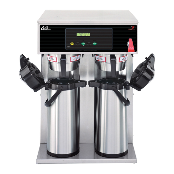
- Page 1 USER GUIDE G3 D1000 Series Twin Airpot Coffee Brewing System “Tall” version shown READ AND SAVE THESE INSTRUCTIONS NOTICE TO INSTALLER: Please leave this booklet with the machine.
-
Page 2: Table Of Contents
..............IP53 ..........................ES53 ........................ES54 ........................................................................................EC5 ..............................Contact Information Wilbur Curtis Co., Inc. 6913 Acco Street | Montebello, CA 90640 US Phone: 323-837-2300 | Toll Free: 800-421-6150 Email: csrassistance@wilburcurtis.com | Web: www.wilburcurtis.com . - 4:00 . PT Email: techsupport@wilburcurtis.com... -
Page 3: Fs29
KEY FEATURES/SPECIFICATIONS/SYSTEM REQUIREMENTS FS29 Key Features • Precise Gourmet Control Over All Critical Functions — The G3 Digital Control Module provides you the expertise to brew premium gourmet coffee with ease. • Cold water brew lockout prevents brewing when water temperature is below set level. •... -
Page 4: Is2
INSTRUCTIONS could result in personal injury or void the warranty. • This appliance is designed for commercial use. Any service other than cleaning and preventive maintenance should be performed by an authorized Wilbur Curtis service technician. • serviceable parts inside. - Page 5 IMPORTANT SAFEGUARDS CE Requirements • This appliance must be installed in locations where it can be overseen by trained personnel. • • This appliance is not suitable for outdoor use. • • • This appliance must not be cleaned by water jet. •...
-
Page 6: Ii2
INSTALLATION INSTRUCTIONS WARNING: WARNING: Improper electrical connection may result in an electric shock hazard or damage the unit. This brewer must be properly grounded. NOTICE: DO NOT connect this brewer to a hot water supply. The water inlet valve is not rated for hot water. Do not exceed the maximum water pressure stated in the SPECIFICATIONS section. - Page 7 INSTALLATION INSTRUCTIONS II35 Installation Leveling WARNING: Use the leveling legs to level the brewer only. Do not use them to adjust brewer height. Do not extend them higher than necessary. Position the brewer on the counter top. Level it left to right and front to back by turning the bottom of the Connecting the Water Supply Flush the water supply line prior to installation to...
-
Page 8: Ii35
INSTALLATION INSTRUCTIONS II35 Connecting the Brewer Wiring (Units That Come from the Factory Without a Power Cord Attached) WARNING: Do not connect the power cord to the power supply until instructed to do so. Brewers With Power Connector Mounted to the Back compatible with the electrical outlet installed in the Style varies... - Page 9 INSTALLATION INSTRUCTIONS II35 Electrical Connection Connection to a Junction Box WARNING: Turn off power to the junction box at the circuit breaker panel and lock out and tag the circuit breaker before connecting the power cable to the junction box. 18 Connect the power cable wires to the terminals in the junction box and replace the cover.
- Page 10 INSTALLATION INSTRUCTIONS II35 Powering Up the Brewer (cont.) 24 When the water in the tank rises to the correct level, the heating elements will turn on automatically. Depending on the incoming water temperature and the electrical minutes to reach the factory set operating temperature. When the water has heated, Ready to brew will be displayed on the LCD screen.
-
Page 11: Oi23
OPERATING INSTRUCTIONS OI23 Brewing Instructions WARNING - TO AVOID SCALDING, AVOID SPLASHING. Keep body parts clear of the brewer during brewing. Do not remove the brew basket while “Brewing” appears on the display. The G3 brewer is factory preset for optimal performance. The brewer should be ON. -
Page 12: Ci1
CLEANING INSTRUCTIONS WARNING: HOT SURFACES - To avoid injury, allow the brewer and dispenser(s) to cool before cleaning. NOTICE - Do not use cleaning liquids, compounds or powders containing chlorine (bleach) or corrosives. USE OF THESE PRODUCTS WILL VOID THE WARRANTY. Cleaning The Brewer - Daily WARNING: DO NOT immerse the brewer in water or any other liquid. -
Page 13: Ci9
CLEANING INSTRUCTIONS Cleaning the Airpot/Pour Pot (Daily) WARNING: DO NOT immerse the airpot/pour pot or lid assembly in water or any other liquid. Do not place the airpot/pour pot or lid in a dishwasher. Placing a airpot or pour pot in a dishwasher will void the warranty. Start by preparing a mild solution of detergent and warm water. - Page 14 PROGRAMMING GUIDE Curtis To enter programming mode: With unit OFF, press and hold Entering bottom right BREW button (4). Programming mode Then press and release ON/OFF button. Continue to hold down BREW button until Enter Code appears. Enter 4 digit code.
- Page 15 PROGRAMMING GUIDE Programming Options Some menus save and exit automatically when a parameter is updated. Other menus exit to the previous menu when a parameter is saved. To exit, press until EXIT appears on the display, then press Brew by Volume - place, press the appropriate BREW button.
- Page 16 Banner Name - changes the banner name that appears on the display (the factory default is Curtis to choose the letter to change. Then press repeatedly to change the number value.
- Page 17 PROGRAMMING GUIDE Programming Options (cont.) Display Messages - to choose the desired setting, then press to exit. Model Select - changes the model number and number of batches (to match the label on the universal control until the model number matching the model number label on the brewer appears, then press Press until the number of batches matches...
- Page 18 ROUGH-IN DRAWINGS RD35 D1000 Airpot Coffee Brewers 20.00 in [50.8 cm] 2.50 in 16.88 in [6.4 cm] [42.9 cm] Water Supply D1000GH D1000GH 29.25 in 26.38 in [74.3 cm] D1000GH D1000GH D1000GH [67.0 cm] 22.88 in 18.13 in D1000GT 17.13 in D1000GT [58.1 cm] [46.0 cm]...
- Page 19 ILLUSTRATED PARTS LIST IP51 D1000GT/ D1000GH - Main Chassis - Exploded View Water tank assemblies: - 220 Volt, see section IP52 - Dual Voltage, see section IP53 D1000, ILLUSTRATED PARTS/RECOMMENDED PARTS 040319C...
-
Page 20: Ip51
(OPTIONAL, OLDER UNITS WITH SUMP IN BASE) WC-8560 TL9002-10/D1000AP/T LABEL, UCM OVERLAY DUAL D1000GT/H BREW CONE, W/HANDLE ASSY 7.1”D.W/WC- WC-39396 CURTIS LOGO (INCLUDES INNER AND OUTER WC-3316 3317 & WC-3323 ALP/AP LABEL) BREW CONE, W/HANDLE ASSY 6.7”D DLX WC- WC-4426... -
Page 21: Ip52
ILLUSTRATED PARTS/RECOMMENDED PARTS IP52 WC-75285 - Tank Assembly Water Level Probe Detail (Older Units) WC-75285 - Tank Assembly - Parts List ITEM # PART # DESCRIPTION ITEM # PART # DESCRIPTION WC-75285 TANK, COMPLETE D1000GT/H W/ULTEM FITTINGS WC-4382* GUARD, SHOCK HTNG ELMNT DOUBLE WC-37008 KIT, TANK LID ROUND (INCLUDES GASKET) THERMOSTAT, HI LIMIT HEATER CONTROL DPST... -
Page 22: Ip53
ILLUSTRATED PARTS/RECOMMENDED PARTS IP53 WC-75284 - Tank Assembly Water Level Probe Detail (Older Units) WC-75284 - Tank Assembly - Parts List ITEM # PART # DESCRIPTION ITEM # PART # DESCRIPTION TANK, COMPLETE D1000GT/H DV W/ULTEM WC-4382* GUARD, SHOCK HTNG ELMNT DOUBLE WC-75284 FITTINGS THERMOSTAT, HI LIMIT HEATER CONTROL DPST... -
Page 23: Es53
ELECTRICAL SCHEMATICS ES53 D1000GT12, D1000GH13 D1000-10, ELECTRICAL SCHEMATIC 050217NC... -
Page 24: Es54
ELECTRICAL SCHEMATICS ES54 D1000GH62, D1000GT63 D1000-60, ELECTRICAL SCHEMATIC 050217NC... - Page 25 TROUBLESHOOTING GUIDE WARNING: Electric Shock Hazard - Scald and Burn Hazard - IMPORTANT: always Valve Test Procedure ELECTRICAL SCHEMATIC Troubleshooting Guidelines ERROR CODES • • • Use this troubleshooting guide along with the appropriate ELECTRICAL SCHEMATIC. • Valve Test Procedure in either direction Water Not Hot Enough replace the temperature sensor...
- Page 26 TROUBLESHOOTING GUIDE During Brewing ELECTRICAL SCHEMATIC No Power - Display Not Lit Water Tank Does Not Fill Brewer Does Not Start When Brew Button is Pressed Brewing Brewing Sensor Error Message...
- Page 27 TROUBLESHOOTING GUIDE Water Tank Does Not Fill IMPORTANT: Coffee/Tea Too Strong Dispenser Not Filled To Normal Level During Brewing Dispenser Not Filled To Normal Level During Brewing SPECIFICATIONS sure that the spray head is correctly aligned and that the tubing is routed properly to allow for maximum water ELECTRICAL SCHEMATIC...
- Page 28 TROUBLESHOOTING GUIDE All Of The Time ELECTRICAL SCHEMATIC No Water/Tea Flows From Brewer During Brewing Water Tank Does Not Fill ELECTRICAL SCHEMATIC Low Water Flow Warning Water Level Error Message Water Level Error Message ERROR CODES SPECIFICATIONS...
- Page 29 TROUBLESHOOTING GUIDE TG39 Water Does Not Heat At All Check to see if the water level in the tank is in contact with the water level probe. If not, see Tank Does Not Fill. • The water will not heat unless it is in contact with the probe. If the water heats, but is not hot enough, see Water Not Hot Enough.
-
Page 30: Ec5
ERROR CODES System Fault Messages An error message will appear on the screen in the event of a malfunction under the following conditions: ERROR MESSAGE WARNING DESCRIPTION CAUSE Water Level Error 1-(800)-000-0000 1-(800)-000-0000 1-(800)-000-0000... - Page 31 Return Merchandise Authorization (RMA): All returned equipment must be properly re-packaged in the original carton and received by Curtis within 45 days following the issuance of a RMA. NO UNITS OR PARTS WILL BE ACCEPTED WITHOUT A RETURN MERCHANDISE AUTHORIZATION (RMA).
Need help?
Do you have a question about the G3 D1000 Series and is the answer not in the manual?
Questions and answers