
Related Manuals for Curtis G4 Series


Summary of Contents for Curtis G4 Series
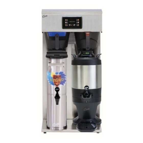
- Page 1 USER GUIDE G4 High Volume Combo Brewers Dispensers not included READ AND SAVE THESE INSTRUCTIONS NOTICE TO INSTALLER: Please leave this booklet with the machine. 053119D FC3 - G4CBHS/G4CBHT, FRONT COVER F-10002 revB...
-
Page 2: Table Of Contents
..........................ES7 ..........................ES8 ....................................................................................................................EC1 ..............................Contact Information Wilbur Curtis Co., Inc. 6913 Acco Street | Montebello, CA 90640 US Phone: 323-837-2300 | Toll Free: 800-421-6150 Email: csrassistance@wilburcurtis.com | Web: www.wilburcurtis.com . - 4:00 . PT Email: techsupport@wilburcurtis.com 122717A... -
Page 3: Fs3
KEY FEATURES/SPECIFICATIONS/SYSTEM REQUIREMENTS Key Features • Multiple Beverage Options – Allows you to brew Coffee, Iced Coffee and Iced Tea from one model. • Generation Four (G4) Digital Control Module – Large, 4.3” touchscreen. Icon-driven interface streamlines operation. Provides precise control of all critical brewing functions. •... -
Page 4: Is2
INSTRUCTIONS could result in personal injury or void the warranty. • This appliance is designed for commercial use. Any service other than cleaning and preventive maintenance should be performed by an authorized Wilbur Curtis service technician. • serviceable parts inside. - Page 5 IMPORTANT SAFEGUARDS CE Requirements • This appliance must be installed in locations where it can be overseen by trained personnel. • • This appliance is not suitable for outdoor use. • • • This appliance must not be cleaned by water jet. •...
-
Page 6: Ii2
INSTALLATION INSTRUCTIONS WARNING: WARNING: Improper electrical connection may result in an electric shock hazard or damage the unit. This appliance must be properly grounded. NOTICE: DO NOT connect this appliance to a hot water supply. The water inlet valve is not rated for hot water. - Page 7 INSTALLATION INSTRUCTIONS II35 Installation Leveling WARNING: Use the leveling legs to level the brewer only. Do not use them to adjust brewer height. Do not extend them higher than necessary. Position the brewer on the counter top. Level it left to right and front to back by turning the bottom of the Connecting the Water Supply Flush the water supply line prior to installation to...
-
Page 8: Ii35
INSTALLATION INSTRUCTIONS II35 Connecting the Brewer Wiring (Units That Come from the Factory Without a Power Cord Attached) WARNING: Do not connect the power cord to the power supply until instructed to do so. Brewers With Power Connector Mounted to the Back compatible with the electrical outlet installed in the Style varies... - Page 9 INSTALLATION INSTRUCTIONS II35 Electrical Connection Connection to a Junction Box WARNING: Turn off power to the junction box at the circuit breaker panel and lock out and tag the circuit breaker before connecting the power cable to the junction box. 18 Connect the power cable wires to the terminals in the junction box and replace the cover.
- Page 10 INSTALLATION INSTRUCTIONS II35 Powering Up the Brewer (cont.) 24 When the water in the tank rises to the correct level, the heating elements will turn on automatically. Depending on the incoming water temperature and the electrical minutes to reach the factory set operating temperature. When the water has heated, Ready to brew will be displayed on the LCD screen.
-
Page 11: Oi2
OPERATING INSTRUCTIONS Brewing Instructions WARNING - TO AVOID SCALDING, AVOID SPLASHING. Keep body parts clear of the brewer during brewing. Do not remove the brew basket while “Brewing” appears on the display. WARNING - DO NOT refrigerate unused tea overnight for later consumption. The G4 Combo Brewer is factory preset for optimal performance. -
Page 12: Ci1
CLEANING INSTRUCTIONS WARNING: HOT SURFACES - To avoid injury, allow the brewer and dispenser(s) to cool before cleaning. NOTICE - Do not use cleaning liquids, compounds or powders containing chlorine (bleach) or corrosives. USE OF THESE PRODUCTS WILL VOID THE WARRANTY. Cleaning The Brewer - Daily WARNING: DO NOT immerse the brewer in water or any other liquid. -
Page 13: Ci5
CLEANING INSTRUCTIONS Cleaning the 1.0 Gallon or 1.5 Gallon Thermal Dispensers (Daily) WARNING: DO NOT immerse the thermal server or its lid assembly in water or any other liquid. Do not place the thermal server or lid in a dishwasher. Placing a thermal server in a dishwasher will void the warranty. To avoid damage, DO NOT use a brush to clean the faucet or the inside of the faucet shank (outlet). - Page 14 CLEANING INSTRUCTIONS Cleaning the Faucet Parts and Gauge Glass (cont.) Sanitize - After rinsing, place all faucet and gauge parts in a sink to be sanitized. Immerse them in a commercial sanitizer suitable for food grade applications. Sanitize according to the WASH directions on the package.
-
Page 15: Ci6
CLEANING INSTRUCTIONS Cleaning the Tea Dispenser (Daily) Cleaning the Container Prepare a mild solution of detergent and warm water. Remove the dispenser from the brewer and remove the lid. Rinse. Wash - Wipe the exterior surfaces with a sponge and the detergent solution to remove spills and debris. - Page 16 Control symbols - all symbols may not be present at the same time Return to Home Undo Curtis logo Scroll left/right previous Entering Programming Mode The ACCESS CODE screen will appear. The menu icons. The icons vary based on the model appear.
- Page 17 PROGRAMMING GUIDE Programming SELECTIONS FOR COFFEE BREWER MODELS Model Select Recipes Control Settings Brew Settings Settings Summary Exit Coffee ® Gemini Gemini IF ™ GEMX One Batch Single Gourmet Std Two Batch Twin Light Roast By Volume/Time Three Batch Dark Roast ™...
- Page 18 PROGRAMMING GUIDE USB - Easy Programming program each step individually using the touchscreen. This process also makes it easy to quickly standardize the IMPORTANT: completely Uploading the Software to the Flash Drive as desired. Downloading the Software to the Brewer from the Flash Drive Select the (identical) brewer you wish to make program changes to.
- Page 19 ROUGH-IN DRAWINGS G4CBHS - G4 Single High Volume Combo Brewer 9.11 in 23.1 cm 36.71 in 93.2 cm 24.31 in 23.65 in 22.99 in 61.7 cm 60.1 cm 58.4 cm 5.43 in 13.8 cm 10.00 in 20.84 in 1.29 in 52.9 cm 25.4 cm 3.3 cm...
- Page 20 ILLUSTRATED PARTS/RECOMMENDED PARTS G4CBHS - Main Chassis - Exploded View SEE SECTION IP25 Units equipped with 2 single inlet valves instead of dual inlet valve, shown above *Orientation varies with date of manufacture G4CBHS/G4CBHT, ILLUSTRATED PARTS/RECOMMENDED PARTS 092818D...
-
Page 21: Ip3
ILLUSTRATED PARTS/RECOMMENDED PARTS G4CBHS - Main Chassis - Parts List ITEM # PART # DESCRIPTION ITEM # PART # DESCRIPTION COVER, TOP ALPGT/D500GT/D60GT TLP/TCTS/CBS/ WC-5310 TUBE, 5/16 ID x 1/8W SILICONE GEN USE WC-58117 GEMSS WC-5231 COMPOUND, HEAT SINK 5OZ WC-61607 COVER, FRONT CBHVS TRANSFORMER,120VAC-24V 4.8A W/ LEADS &... - Page 22 ILLUSTRATED PARTS/RECOMMENDED PARTS G4CBHT - Main Chassis - Exploded View SEE SECTION IP26 Units equipped with 2 single inlet valves instead of dual inlet valve, shown above *Orientation varies with date of manufacture G4CBHS/G4CBHT, ILLUSTRATED PARTS/RECOMMENDED PARTS 092818D...
- Page 23 ILLUSTRATED PARTS/RECOMMENDED PARTS G4CBHT - Main Chassis - Parts List ITEM # PART # DESCRIPTION ITEM # PART # DESCRIPTION COVER, TOP SS GEM-12D GEM-612ILD, TL9002, WC-5310 TUBE, 5/16 ID x 1/8W SILICONE GEN USE WC-5421 312IL WC-5231 COMPOUND, HEAT SINK 5OZ WC-61619 COVER, FRONT W/A CBHTV TRANSFORMER,120VAC-24V 4.8A W/ LEADS &...
-
Page 24: Ip25
ILLUSTRATED PARTS/RECOMMENDED PARTS IP25 WC-62080 - Tank Assembly WC-62080 - Tank Assembly - Parts List ITEM # PART # DESCRIPTION ITEM # PART # DESCRIPTION WC-54290DV-102 TANK, ASSY CBHS/CBHS67144 THERMOSTAT, HI LIMIT HEATER CONTROL WC-522 DPST 277V 40A WC-62080 TANK COMPLETE, CBHS/CBHS67144 WC-37365 KIT, FITTING TANK INLET WC-5853-102... -
Page 25: Ip26
ILLUSTRATED PARTS/RECOMMENDED PARTS IP26 WC-62033 - Tank Assembly WC-62033 - Tank Assembly - Parts List ITEM # PART # DESCRIPTION ITEM # PART # DESCRIPTION WC-54287 TANK, ASSY TPS1T/GEMTS WC-1438-101 SENSOR, TEMPERATURE TANK WC-62033 TANK, COMPLETE GEMTS W/ULTEM FITTINGS WC-4382 GUARD, SHOCK HTNG ELMNT DOUBLE WC-37008 KIT, TANK LID ROUND (INCLUDES GASKET) -
Page 26: Es7
ELECTRICAL SCHEMATICS G4CBHS - 110/220 to 120/240 Volts (UPM) Pin Assignments 120V Hot Input 120V Hot Input Brew Valve Right Not Used 120V Neut ral Inlet Valve Not Used Not Used Not Used 10 Not Used 11 Not Used 12 Not Used 13 Dilut ion Right 14 Not Used 15 Bypass Valve Right... -
Page 27: Es8
ELECTRICAL SCHEMATICS G4CBHT - 208 to 240 Volts (UPM) Pin Assignments 120V Hot Input 120V Hot Input Brew Valve Right Brew Valve Left 120V Neut ral Inlet Valve Not Used Not Used Not Used 10 Not Used 11 Not Used 12 Not Used 13 Dilut ion Right 14 Dilut ion Left... - Page 28 TROUBLESHOOTING GUIDE WARNING: Electric Shock Hazard - Scald and Burn Hazard - IMPORTANT: always check all Valve Test Procedure Troubleshooting Guidelines • • • • Valve Test Procedure in either direction Water Not Hot Enough replace the temperature sensor Water Heats More Slowly Than Usual During Brewing...
- Page 29 TROUBLESHOOTING GUIDE No Power - Display Not Lit Water Tank Does Not Fill Brewer Does Not Start When Brew Button is Pressed Brewing Brewing Sensor Error Message...
- Page 30 TROUBLESHOOTING GUIDE Water Tank Does Not Fill IMPORTANT: Coffee/Tea Too Strong Dispenser Not Filled To Normal Level During Brewing Dispenser Not Filled To Normal Level During Brewing sure that the spray head is correctly aligned and that the tubing is routed properly to allow for maximum water All Of The Time...
- Page 31 TROUBLESHOOTING GUIDE No Water/Tea Flows From Brewer During Brewing Water Tank Does Not Fill Low Water Flow Warning Water Level Error Message Water Level Error Message “Internal Error 1” Message on Display “Internal Error 2” Message on Display PROGRAMMING GUIDE...
- Page 32 TROUBLESHOOTING GUIDE Water Does Not Heat At All Check to see if the water level in the tank is in contact with the water level probe. If not, see Tank Does Not Fill. • The water will not heat unless it is in contact with the probe. If the water heats, but is not hot enough, see Water Not Hot Enough.
- Page 33 The G4 control module diagnostics can be used to detect electrical circuit failures in the brewer. When a circuit Using the Diagnostics The MAIN MENU Control Settings. Diagnostics Curtis logo Auto Test to test all circuits. If a button is highlighted green the DIAGNOSTICS Left Auto Test...
-
Page 34: Ec1
ERROR CODES Warning Messages - Allows Brewer to Continue Brewing MESSAGE DISPLAY WARNING DESCRIPTION CAUSE Brew count “Gallons Since Reset” exceeds programmed Maintenance Required Maintenance Required preventative maintenance period. If the Inlet valve remains on longer than XX seconds (during the brew cycle only) and repeats TWICE during that brew cycle. - Page 35 Return Merchandise Authorization (RMA): All returned equipment must be properly re-packaged in the original carton and received by Curtis within 45 days following the issuance of a RMA. NO UNITS OR PARTS WILL BE ACCEPTED WITHOUT A RETURN MERCHANDISE AUTHORIZATION (RMA).
Need help?
Do you have a question about the G4 Series and is the answer not in the manual?
Questions and answers