
Related Manuals for Curtis ThermoPro G3 Series


Summary of Contents for Curtis ThermoPro G3 Series
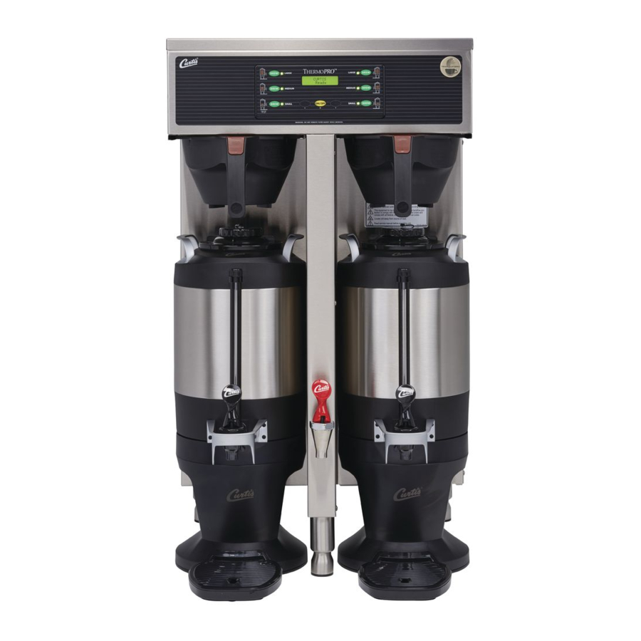
- Page 1 USER GUIDE ® G3 ThermoPro Series 1.5 Gallon Coffee Brewing System READ AND SAVE THESE INSTRUCTIONS NOTICE TO INSTALLER: Please leave this booklet with the machine.
-
Page 2: Table Of Contents
................................................................................................................................................................................................Contact Information Wilbur Curtis Co., Inc. 6913 Acco Street | Montebello, CA 90640 US Phone: 323-837-2300 | Toll Free: 800-421-6150 Email: csrassistance@wilburcurtis.com | Web: www.wilburcurtis.com . - 4:00 . PT Email: techsupport@wilburcurtis.com... -
Page 3: Fs26
KEY FEATURES/SPECIFICATIONS/SYSTEM REQUIREMENTS FS26 Key Features • Easy-to-operate, intuitive G3 Digital control module - provides precise control over all aspects of brewing: time, temperature, volume plus specialty coffee needs from pre-infusion to pulse-brewing to water bypass. • Built-in Self Diagnostic System – Includes real-time feedback of the brewing process and energy saving mode. ®... -
Page 4: Is2
INSTRUCTIONS could result in personal injury or void the warranty. • This appliance is designed for commercial use. Any service other than cleaning and preventive maintenance should be performed by an authorized Wilbur Curtis service technician. • serviceable parts inside. - Page 5 IMPORTANT SAFEGUARDS CE Requirements • This appliance must be installed in locations where it can be overseen by trained personnel. • • This appliance is not suitable for outdoor use. • • • This appliance must not be cleaned by water jet. •...
-
Page 6: Ii2
INSTALLATION INSTRUCTIONS WARNING: WARNING: Improper electrical connection may result in an electric shock hazard or damage the unit. This appliance must be properly grounded. NOTICE: DO NOT connect this appliance to a hot water supply. The water inlet valve is not rated for hot water. -
Page 7: Ii11
INSTALLATION INSTRUCTIONS II11 Installation Leveling WARNING: Use the leveling legs to level the brewer only. Do not use them to adjust brewer height. Do not extend them higher than necessary. Position the brewer on the counter top. Level it left to right and front to back by turning the bottom of the legs. - Page 8 INSTALLATION INSTRUCTIONS II11 Connect the Brewer Wiring (cont.) Installing the Power Plug (units that do not have a pre-installed plug and will be connected to a power Required plug style receptacle) varies with circuit requirements 10 Connect the appropriate type of grounded power plug to the end of the power cord coming from the back of the unit.
- Page 9 INSTALLATION INSTRUCTIONS II11 Powering up the Unit (cont.) IMPORTANT: elevations, reduce the default operating temperature (200°F/92°C) by 2°F/1°C for each 1000 feet (300 m) of elevation above 4000 feet (1200 m). See PROGRAMMING GUIDE. volume, the heating elements will turn on automatically. Depending on the incoming water temperature and requires 20 to 30 minutes to reach the factory set “Ready to Brew”...
-
Page 10: Oi6
OPERATING INSTRUCTIONS Brewing Instructions WARNING - TO AVOID SCALDING, AVOID SPLASHING. Keep body parts clear of the brewer during brewing. Do not remove the brew basket while “Brewing” appears on the display. The G3 ThermoPro Brewer is factory preset for optimal performance. The brewer should be ON. -
Page 11: Ci1
CLEANING INSTRUCTIONS WARNING: HOT SURFACES - To avoid injury, allow the brewer and dispenser(s) to cool before cleaning. NOTICE - Do not use cleaning liquids, compounds or powders containing chlorine (bleach) or corrosives. USE OF THESE PRODUCTS WILL VOID THE WARRANTY. Cleaning The Brewer - Daily WARNING: DO NOT immerse the brewer in water or any other liquid. -
Page 12: Ci5
SANITIZE continued... * For 1.5 gal./5.7 L dispensers use type Z95 (Curtis PN WC-79000) For 1.0 gal./3.8 L dispensers use type Z61 (Curtis PN WC-79003) 1.0/1.5 GALLON THERMAL DISPENSER, CLEANING INSTRUCTIONS... - Page 13 CLEANING INSTRUCTIONS Cleaning the Thermal Dispenser (cont.) Disassemble the faucet - Unscrew the handle/ Style varies bonnet assembly from the top of the faucet and remove it. Inspect the seat cup for wear. Replace the Washer seat cup if it is damaged. Unscrew the cap and guard to dis-assemble.
-
Page 14: Ci9
CLEANING INSTRUCTIONS Cleaning the Airpot/Pour Pot (Daily) WARNING: DO NOT immerse the airpot/pour pot or lid assembly in water or any other liquid. Do not place the airpot/pour pot or lid in a dishwasher. Placing a airpot or pour pot in a dishwasher will void the warranty. Start by preparing a mild solution of detergent and warm water. - Page 15 PROGRAMMING GUIDE Wilbur Curtis To enter programming mode: With unit OFF, press and hold Wilbur Curtis bottom right BREW button (4). Ready to Brew* Then press and release ON/OFF button (2). Continue to hold down BREW button until Enter Code appears.
- Page 16 PROGRAMMING GUIDE Programming Options See the previous page for instructions on accessing each individual menu. Some menus save and exit automatically when a parameter is updated. Other menus exit to the previous menu when a parameter is saved. To exit, press until EXIT appears on the display, then press Global Recipes Menu Select from the following coffee recipes: Gourmet STD (standard), Light Roast, Dark Roast, High Yield, Filter...
- Page 17 PROGRAMMING GUIDE Non-Brew Programming Menu Non-Brew Prog Banner Name Warmers Default Brew Count Total QT Alarm On/Off <-- Select --> <-- Select --> <-- Select --> <-- Select --> <-- Select --> Press Select Select Select Select Temperature Cold Brew Lock Warmers Auto-Off Display Brew Time Satellite Color...
- Page 18 Banner Name - changes the company name that appears on the display. The factory default is Curtis. No name appears when all blanks are entered. Once accessed, press to choose the letter to change.
- Page 19 PROGRAMMING GUIDE Non-Brew Programming Menu (cont.) Display Brew Time - turns the display of the brew time during brewing On or Off. The factory default setting is On. Once accessed, press to choose the desired setting, then press to exit. Display Messages - turns display of the message “Rinse Server Before Brewing”...
- Page 20 PROGRAMMING GUIDE Brew Button Programming Menu (cont.) Brew by Time - adjusts the amount of coffee brewed by time rather than by volume. The factory default to change the number value. Press repeatedly to change the number value. Press repeatedly to exit.
- Page 21 PROGRAMMING GUIDE Model Select Menu - changes the model number and number of batches (to match the label on the universal control module, the factory default is Gemini-Twin, One batch). Once accessed, press until the model number matching the model number label on the brewer appears, then press Press until the number of to exit.
- Page 22 ROUGH-IN DRAWINGS RD32 TP2S - Single Coffee Brewer 20.75 in [52.7 cm] 35.13 in [89.2 cm] 24.00 in [60.0 cm] 8.38 in 11.13 in [21.0 cm] [28.3 cm] 4.00 in [10.2 cm] TP2T - Twin Coffee Brewer 20.75 in 35.13 in [52.7 cm] [89.2 cm] 24.00 in...
- Page 23 ILLUSTRATED PARTS LIST IP49 TP2S - Main Chassis - Exploded View Water tanks assemblies - See section IP43 for single voltage models - See section IP44 for dual voltage models TP2, ILLUSTRATED PARTS/RECOMMENDED PARTS 092019D...
- Page 24 GASKET, 1.00OD X .625 I.D. X .030 THK WHITE WC-43089 b WC-39416 OPTION THERMOPRO CURTIS EPDM 70 SHORE WC-4213-P a WC-39444 LABEL, UCM OVERLAY 3-BATCH TP2S CURTIS NUT, 5/8 LOCK PLATED WC-4212-02 b RELAY, SOLID STATE 280V/40A W/ HEATSINK NUT, 5/8-18 JAM PLASTIC WC-8559 AND QUICK DISCONNECTS WC-4412 SCREW, 10-32x3/16”...
- Page 25 ILLUSTRATED PARTS/RECOMMENDED PARTS IP49 TP2T - Main Chassis - Exploded View Water tank assembly, see section IP45 TP2, ILLUSTRATED PARTS/RECOMMENDED PARTS 092019D...
- Page 26 TUBE, 1/2 ID x 1/8W SILICONE GEN USE LABEL, UCM OVERLAY DUAL TWIN 3-BATCH CONTROL MODULE, UCM 120V TP2S/TP2T 7A # WC-723 1,2,3 WC-39393 THERMOPRO CURTIS LOGO GEMSS/GEMTS LABEL, UCM OVERLAY TWIN 1-BTCH OPTION CONTROL MODULE, UCM 220V TP2S/TP2T/ WC-728 4 WC-39414...
- Page 27 ILLUSTRATED PARTS LIST IP43 WC-62032 - Tank Assembly WC-62032 - Tank Assembly - Parts List ITEM # PART # DESCRIPTION ITEM # PART # DESCRIPTION WC-62032 TANK, COMPLETE TP2S ULTEM FITTNGS THERMOSTAT, HI LIMIT HEATER CONTROL DPST WC-522* 277V 40A WC-5853-102 COVER, TOP HEATING TANK GEN USE WC-43055*...
- Page 28 ILLUSTRATED PARTS LIST IP44 WC-62031 - Tank Assembly WC-62031 - Tank Assembly - Parts List ITEM # PART # DESCRIPTION ITEM # PART # DESCRIPTION WC-62031 TANK, COMPLETE TP2S (2) 1600W/120V THERMOSTAT, HI LIMIT HEATER CONTROL WC-522 DPST 277V 40A WC-5853-102 COVER, TOP HEATING TANK GEN USE WC-43055...
- Page 29 ILLUSTRATED PARTS/RECOMMENDED PARTS IP45 WC-62030 - Tank Assembly WC-62030 - Tank Assembly - Parts List ITEM # PART # DESCRIPTION ITEM # PART # DESCRIPTION WC-62030 TANK, COMPLETE TP2T ULTEM FITTNGS WC-4382* GUARD, SHOCK HTNG ELMNT DOUBLE WC-37008 KIT, TANK LID ROUND (INCLUDES GASKET) THERMOSTAT, HI LIMIT HEATER CONTROL DPST WC-522* 277V 40A...
- Page 30 ELECTRICAL SCHEMATICS ES31 SINGLE, DOMESTIC, 220 VOLT GTPS-10, ELECTRICAL SCHEMATIC 061918B...
- Page 31 ELECTRICAL SCHEMATICS ES32 SINGLE, EXPORT UCM Pin Assignments 20 Pin Connector GRINDER INTERLOCK COMMON-SOLID STATE RELAY & GRINDER +5 VDC BREW CONE LOCK NOT USED INLET VALVE BYPASS VALVE NOT USED WARMER NOT USED NOT USED NOT USED TANK TEMPERATURE SENSOR ELECTRICAL RATING TABLE TANK TEMPERATURE SENSOR # of...
- Page 32 ELECTRICAL SCHEMATICS ES33 SINGLE, DOMESTIC, DUAL VOLTAGE UCM Pin Assignments 20 Pin Connector GRINDER INTERLOCK COMMON-SOLID STATE RELAY & GRINDER +5 VDC BREW CONE LOCK NOT USED INLET VALVE BYPASS VALVE NOT USED WARMER NOT USED NOT USED NOT USED TANK TEMPERATURE SENSOR TANK TEMPERATURE SENSOR UCM GROUND...
- Page 33 ELECTRICAL SCHEMATICS ES34 TWIN, DOMESTIC...
- Page 34 ELECTRICAL SCHEMATICS ES35 TWIN, 3 PHASE WITH TRANSFORMER...
- Page 35 ELECTRICAL SCHEMATICS ES36 TWIN, 3 PHASE WITHOUT TRANSFORMER...
- Page 36 ELECTRICAL SCHEMATICS ES37 TWIN, EXPORT ELECTRICAL RATING TABLE # of Tank Element Voltage Amps Wa s Hertz # of Tank Model Conductor Phase Ra ng Elements Wires GEMTS30 24.7 5683 50/60 2500W/220V TP2T30 24.2 5574 50/60 2500W/220V TPC2T30 24.2 5574 50/60 2500W/220V TP1T30...
- Page 37 TROUBLESHOOTING GUIDE WARNING: Electric Shock Hazard - Scald and Burn Hazard - IMPORTANT: always Valve Test Procedure ELECTRICAL SCHEMATIC Troubleshooting Guidelines ERROR CODES • • • Use this troubleshooting guide along with the appropriate ELECTRICAL SCHEMATIC. • Valve Test Procedure in either direction Water Not Hot Enough replace the temperature sensor...
- Page 38 TROUBLESHOOTING GUIDE During Brewing ELECTRICAL SCHEMATIC No Power - Display Not Lit Water Tank Does Not Fill Brewer Does Not Start When Brew Button is Pressed Brewing Brewing Sensor Error Message...
- Page 39 TROUBLESHOOTING GUIDE Water Tank Does Not Fill IMPORTANT: Coffee/Tea Too Strong Dispenser Not Filled To Normal Level During Brewing Dispenser Not Filled To Normal Level During Brewing SPECIFICATIONS sure that the spray head is correctly aligned and that the tubing is routed properly to allow for maximum water ELECTRICAL SCHEMATIC...
- Page 40 TROUBLESHOOTING GUIDE All Of The Time ELECTRICAL SCHEMATIC No Water/Tea Flows From Brewer During Brewing Water Tank Does Not Fill ELECTRICAL SCHEMATIC Low Water Flow Warning Water Level Error Message Water Level Error Message ERROR CODES SPECIFICATIONS...
- Page 41 TROUBLESHOOTING GUIDE Water Does Not Heat At All Check to see if the water level in the tank is in contact with the water level probe. If not, see Tank Does Not Fill. • The water will not heat unless it is in contact with the probe. If the water heats, but is not hot enough, see Water Not Hot Enough.
- Page 42 ERROR CODES System Fault Messages An error message will appear on the screen in the event of a malfunction under the following conditions: ERROR MESSAGE WARNING DESCRIPTION CAUSE Water Level Error G3 BREWER, ERROR CODES 042017A...
- Page 43 Return Merchandise Authorization (RMA): All returned equipment must be properly re-packaged in the original carton and received by Curtis within 45 days following the issuance of a RMA. NO UNITS OR PARTS WILL BE ACCEPTED WITHOUT A RETURN MERCHANDISE AUTHORIZATION (RMA).
Need help?
Do you have a question about the ThermoPro G3 Series and is the answer not in the manual?
Questions and answers