Table of Contents
Advertisement
Quick Links
Advertisement
Table of Contents

Related Manuals for Aerotech TM3


Summary of Contents for Aerotech TM3
-
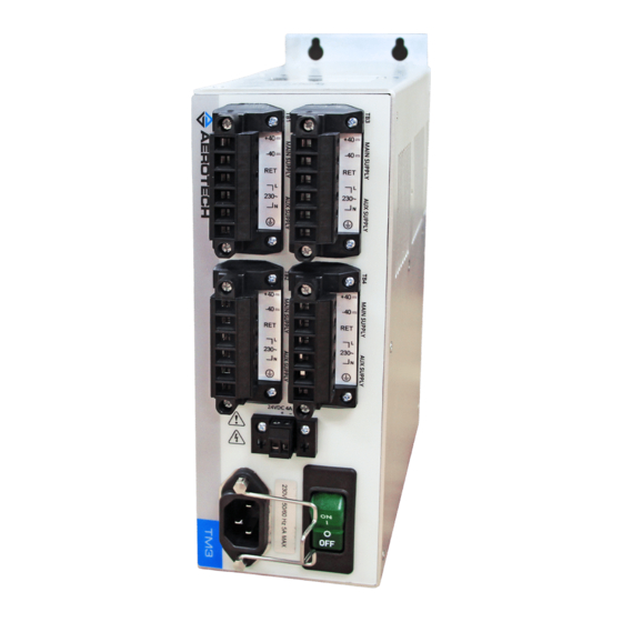
Page 1: Tm3 Hardware Manual
TM3 Hardware Manual Revision: 2.02.00... - Page 2 This manual contains proprietary information and may not be reproduced, disclosed, or used in whole or in part without the express written permission of Aerotech, Inc. Product names mentioned herein are used for identification purposes only and may be trademarks of their respective companies.
-
Page 3: Table Of Contents
Table of Contents List of Figures List of Tables EU Declaration of Conformity Agency Approvals Safety Procedure and Warnings Chapter 1: TM3 Transformer Module 1.1. Electrical Specifications 1.2. Installation and Mounting 1.2.1. Handling and Transportation 1.2.2. Installation 1.2.3. Mechanical Specifications 1.2.4. -
Page 4: List Of Figures
TM3 Hardware Manual Table of Contents List of Figures Figure 1-1: TM3 Transformer Module Figure 1-2: TM3 Dimensions Figure 1-3: System Interconnect Example (HPe) Figure 1-4: System Interconnect Example (CP) Figure 1-5: System Interconnect Example (MP) Figure 1-6: System Interconnect Example (CL) -
Page 5: List Of Tables
Power Output Mating Connector Table 1-6: +24 VDC Output Connections Table 1-7: +24 VDC Output Mating Connector Table 1-8: Soft-Start/Voltage Selector Switch Settings Table 1-9: Symptoms, Causes, and Solutions Table 1-10: TM3 Fuse Replacement Part Numbers Table 1-11: Preventative Maintenance www.aerotech.com... - Page 6 TM3 Hardware Manual Table of Contents This page intentionally left blank. www.aerotech.com...
-
Page 7: Eu Declaration Of Conformity
Table of Contents TM3 Hardware Manual EU Declaration of Conformity Manufacturer Aerotech, Inc. Address 101 Zeta Drive Pittsburgh, PA 15238-2811 Product Model/Types This is to certify that the aforementioned product is in accordance with the applicable requirements of the following Directive(s):... -
Page 8: Agency Approvals
U8 068995 0026 Rev. 00 Standards: UL 61010-1:2012; CAN/CSA-C22.2 No. 61010-1:2012 Visit https://www.tuev-sued.de/product-testing/certificates to view Aerotech's TÜV SÜD certificates. Type the certificate number listed above in the search bar or type "Aerotech" for a list of all Aerotech certificates. www.aerotech.com... -
Page 9: Safety Procedure And Warnings
Safety Procedure and Warnings This manual tells you how to carefully and correctly use and operate the TM3. Read all parts of this manual before you install or operate the TM3 or before you do maintenance to your system. To prevent injury to you and damage to the equipment, obey the precautions in this manual. - Page 10 TM3 Hardware Manual Table of Contents This page intentionally left blank. www.aerotech.com...
-
Page 11: Chapter 1: Tm3 Transformer Module
24 VDC power supply that provides the user with 24 VDC output with a current capacity of up to 4 A (up to 1 A on TM3s purchased before April 2016). Other features of the TM3 include a soft-start circuit to limit inrush current and a voltage selector that can be configured for AC input voltages of 100 VAC, 115 VAC, 200 VAC, or 230 VAC. -
Page 12: Table 1-1: Tm3 Configurations And Options
TM3 Hardware Manual Introduction and Configuration The TM3 is built according to the configuration and options selected when the TM3 was ordered. Table 1-1: TM3 Configurations and Options AC Power Input (factory configured) 115 VAC 100 VAC 230 VAC 200 VAC... -
Page 13: Electrical Specifications
Introduction and Configuration TM3 Hardware Manual 1.1. Electrical Specifications Electrical specifications for the TM3 are listed in Table 1-2. Table 1-2: Electrical Specifications Transformer Aerotech EAX01007 Transformer (standard) AC Input Configurations 100 VAC, 115 VAC, 200 VAC or 230 VAC... -
Page 14: Installation And Mounting
The Aerotech TM3 transformer module can be easily handled by firmly grasping the TM3 chassis itself. Be sure to grip the chassis firmly because the finish on the TM3 can be slippery. Do not attempt to hold or transport the TM3 by grasping onto cables or other hardware. When transporting the TM3 transformer module, it should be placed into a protective plastic bag and then into a box containing an appropriate packing material. -
Page 15: Figure 1-2: Tm3 Dimensions
Introduction and Configuration TM3 Hardware Manual Figure 1-2: TM3 Dimensions Table 1-3: Mechanical Specifications Weight 5.72 kg (12.6 lbs) Mounting Requirements Rack or Enclosure mounting is required www.aerotech.com Chapter 1... -
Page 16: Environmental Specifications
TM3 Hardware Manual Introduction and Configuration 1.2.4. Environmental Specifications Temperature: Ambient Operating: 5° - 40°C (41° - 104°F) Storage: -20° - 70°C (-4° - 158°F) Humidity: Maximum relative humidity is 80% for temperatures up to 31°C. Decreasing linearly to 50% relative humidity at 40°C. Non condensing. -
Page 17: System Interconnection
Introduction and Configuration TM3 Hardware Manual 1.2.5. System Interconnection System interconnection examples are shown below but cables can be purchased from Aerotech. Figure 1-3: System Interconnect Example (HPe) www.aerotech.com Chapter 1... -
Page 18: Figure 1-4: System Interconnect Example (Cp)
TM3 Hardware Manual Introduction and Configuration Figure 1-4: System Interconnect Example (CP) Chapter 1 www.aerotech.com... -
Page 19: Figure 1-5: System Interconnect Example (Mp)
Introduction and Configuration TM3 Hardware Manual Figure 1-5: System Interconnect Example (MP) www.aerotech.com Chapter 1... -
Page 20: Figure 1-6: System Interconnect Example (Cl)
TM3 Hardware Manual Introduction and Configuration Figure 1-6: System Interconnect Example (CL) Chapter 1 www.aerotech.com... -
Page 21: Figure 1-7: System Interconnect Example (Ml)
Introduction and Configuration TM3 Hardware Manual Figure 1-7: System Interconnect Example (ML) www.aerotech.com Chapter 1... -
Page 22: Figure 1-8: System Interconnect Example (Nmark Cls)
TM3 Hardware Manual Introduction and Configuration Figure 1-8: System Interconnect Example (Nmark CLS) Chapter 1 www.aerotech.com... -
Page 23: Figure 1-9: System Interconnect Example (Gl4)
Introduction and Configuration TM3 Hardware Manual Figure 1-9: System Interconnect Example (GL4) www.aerotech.com Chapter 1... -
Page 24: Figure 1-10: System Interconnect Example (Xl4S)
TM3 Hardware Manual Introduction and Configuration Figure 1-10: System Interconnect Example (XL4s) Chapter 1 www.aerotech.com... -
Page 25: Ac Power Input
1.2.6. AC Power Input AC power is supplied to the TM3 via the AC inlet located next to the power switch / breaker. This connection is made through a standard line cord supplied with the TM3 transformer module. The AC power input ratings are listed on the power label on the TM3 transformer module. -
Page 26: Vdc Output [Ps24-1]
2-Pin Terminal Block ECK01110 1754449 0.5 - 0.6 12-30 [3.3 - 0.0516] N O T E : For a TM3 purchased before April 2016: The +24 VDC output has a maximum current output of 1 amps @ 20º C. Chapter 1 www.aerotech.com... -
Page 27: Soft-Start Voltage Selector Overview
W A R N I N G : S1 through S4 must be set for the applied AC power input voltage. Setting S1 through S4 incorrectly may result in damage to the system. W A R N I N G : Disconnect power to the TM3 before changing voltage selector switch settings (S1 through S4). -
Page 28: Operation
1.3. Operation When power is applied to the TM3 transformer box and the power switch is in the ON position the Green power switch will be illuminated. The power switch can also be left on and the power to the TM3 transformer module can be turned ON and OFF remotely. -
Page 29: Maintenance
W A R N I N G : No user serviceable parts inside. D A N G E R : Disconnect power to the TM3 main supply before servicing. D A N G E R : Risk of electric shock. -
Page 30: Troubleshooting
The TM3 transformer Module contains two user replaceable fuses (F1 & F2) located on the Soft-Start / Voltage Select board. Both fuses are located in the primary circuit of the TM3 transformer and function to protect the transformer against shorts and severe overloads on the transformer output. Both fuses are Slow Blow type fuses in order to handle the high inrush currents when the TM3 is turned on. -
Page 31: Preventative Maintenance
In addition, uncouple or otherwise prevent motor-coupled machinery from moving the motor during service. N O T E : Do not use the TM3 (all Aerotech equipment) in a manner not specified by Aerotech, Inc. Table 1-11: Preventative Maintenance... - Page 32 TM3 Hardware Manual Introduction and Configuration This page intentionally left blank. Chapter 1 www.aerotech.com...
-
Page 33: Appendix A: Warranty And Field Service
Aerotech makes no warranty that its products are fit for the use or purpose to which they may be put by the buyer, whether or not such use or purpose has been disclosed to Aerotech in specifications or drawings previously or subsequently provided, or whether or not Aerotech’s... - Page 34 Aerotech's approval. On-site Warranty Repair If an Aerotech product cannot be made functional by telephone assistance or by sending and having the customer install replacement parts, and cannot be returned to the Aerotech service center for repair, and if Aerotech determines the problem could be warranty-related, then the following policy applies:...
-
Page 35: Appendix B: Revision History
Section 1.2.8. Updated voltage specifications: Chapter 1: TM3 Transformer Module, Section 1.1., Table 1-1, Section 1.2.9., Section 1.4.2. 2.00.00 Revision changes have been archived. If you need a copy of this revision, contact Aerotech 1.01.00 Global Technical Support. 1.00.00 www.aerotech.com Appendix B... - Page 36 TM3 Hardware Manual Revision History This page intentionally left blank. Appendix B www.aerotech.com...
-
Page 37: Index
Index TM3 Hardware Manual Index Line Cord Options 2014/35/EU Mechanical Specifications AC Power Input Axis Split Nmark CLS Bus Voltage 1 & 2 Optional Brake Cable Cable Type Check chassis for loose or damaged parts / hardware Power Supply Check for fluids or electrically conductive... - Page 38 TM3 Hardware Manual Index This page intentionally left blank. www.aerotech.com...
Need help?
Do you have a question about the TM3 and is the answer not in the manual?
Questions and answers