Table of Contents
Advertisement
Quick Links
Advertisement
Table of Contents

Related Manuals for Osram DALI Professional Controller-4


Summary of Contents for Osram DALI Professional Controller-4
- Page 1 DALI Professional Controller-4 Control unit Operating instructions...
-
Page 3: Table Of Contents
Contents Safety....................4 General.instructions. Safety.instructions. Description..................5 Purpose.and.application. Configuration. Design. Connections.. Pushbutton. LED.displays. Installation..................8 Fasten.control.unit. Connecting.the.control.unit. Safety.instructions. Preparing.the.wiring. Relays. Number.of.pushbuttons.and.sensor.couplers. Pushbutton. Connection.diagram. System.overview. Operation..................13 Basic.state. Construction.Site.mode. Plug.&.Play.mode. Further.operating.functions. Offline.mode.(power.supply.via.the.USB.interface). Behaviour.after.a.power.failure. Appendix..................18 Technical.data. Applicable.standards. Notes. -
Page 4: Safety
DALI.Professional.Controller-4 Safety Safety General instructions The.control.unit.must.only.be.installed.and.put.into.operation.by.a.qualified.electrician. The.applicable.safety.regulations.and.accident.prevention.regulations.must.be.ob- served. Safety instructions WARNING! Exposed,.live.cables. Danger.of.electric.shock! •. Only.work.on.the.control.unit.when.it.is.de-energised. CAUTION! Destruction.of.the.control.unit.and.other.devices.through.incorrect.mounting! •. The.control.unit.should.only.be.mounted.in.switch.cabinets.(DIN.43880). •. The.DALI.standard.as.per.IEC.62386.must.be.complied.with. III.2010... -
Page 5: Description
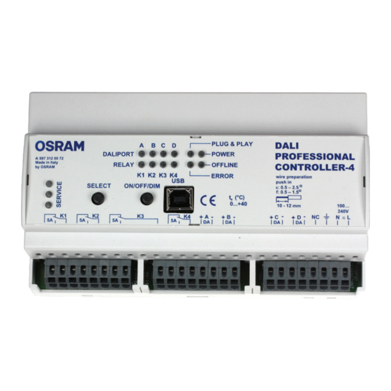
DALI.Professional.Controller-4 Description Description Purpose and application The.DALI.Professional.control.unit.makes.scene-based.operations.and.daylight/pres- ence-dependent.operations.possible. The.control.unit.can.control.up.to.256.(4x64).DALI-operating.devices.via.4.DALI.lines. and.functions.with.any.other.device.of.the.DALI.Professional.product.family..For.more. detailed.information.on.DALI,.see.http://www.dali-ag.org/. The.gateway.is.designed.for.installation.on.35.mm.DIN.rails.in.switch.cabinets. Configuration In.order.to.make.use.of.the.control.unit‘s.full.functionality.(e.g..brightness.control,. scenes,.sequences,.colour.control,.addressing),.you.must.have.a.PC.configured.with. the.DALI.Professional.software.(see.the.separate.software.instructions). Simple.light.operations.(switching.on/off,.dimming).can.be.carried.out.without.previous. configuration.(see.„Operation“.in.these.operating.instructions): •. With.the.pushbuttons.directly.on.the.device.(„Construction.Site.mode“) •. With.the.buttons.directly.on.the.device.and.the.motion.sensors.(„Plug.&.Play.Mode“) Design The.control.unit.is.made.up.of.the.following.components: Connections •. Power.supply.(A) •. DALI.lines.(two-pole).A,.B,.C,.D.(B) •. Relay.contacts.K1,.K2,.K3,.K4.(C) •. USB.interface.(type.B).for.PC.connection.(J). Pushbutton •. “SELECT”.pushbutton.(E) •. „ON/OFF/DIM“.pushbutton.(F) III.2010... -
Page 6: Led.displays
DALI.Professional.Controller-4 Description LED displays „DALIPORT“ (G): Status of the DALI A, B, C, D lines: Meaning Mains.voltage.present,.DALI.power.supply.active. No.mains.voltage.present,.DALI.power.supply.inactive.(control.unit. supplied.only.through.USB). Flashes Short.circuit.within.the.DALI.circuit.(voltage.0.V). Sparks Overvoltage.in.the.DALI.circuit.(voltage.>.20.V). „RELAY“ (H): Status of the relay outputs K1, K2, K3, K4 Meaning Relay.energised. Relay.de-energised.(switching.state.as.on.imprint). Flashes See."Construction.Site.Mode".in."Operation". LEDs for status display of the control unit (K) „PLUG.&.PLAY“: Meaning Plug.&.Play.mode.available.(i.e..control.unit.has.not.yet.been.configu-... - Page 7 DALI.Professional.Controller-4 Description „ERROR“ Meaning Lamp.faults.detected. Normal.operation. „SERVICE“:.(D) Meaning On/Off Reserved.for.future.applications III.2010...
-
Page 8: Installation
DALI.Professional.Controller-4 Installation Installation Fasten control unit The.DALI.Professional.control.unit.is.only.intended.to.be.mounted.on.35.mm.DIN.rails. in.a.switch.cabinet,.as.per.DIN.43880..It.requires.an.installation.width.of.9.horizontal. pitch.units.(HP). Proceed.as.follows: Step Task Press.in.lock.clips.until.you.hear.them.lock.with.a."click".sound. Lock.in.the.control.unit.on.the.DIN.rail. Removal:.Using.a.screwdriver,.push.out.the.lock.clips. III.2010... -
Page 9: Connecting.the.control.unit
DALI.Professional.Controller-4 Installation Connecting the control unit Safety instructions WARNING! Protection.Class.I.device. Danger.of.electric.shock! •. Securely.connect.the.protective.earth.(PE). •. Use.B.10.A.or.B.16.A.type.unit.as.circuit.breaker. WARNING! The.DALI.interface.is.insulated.by.a.basic.insulation. Danger.of.electric.shock! •. Use.wires.that.can.handle.power.line.voltages.for.the.entire.DALI.wiring. •. Include.DALI.wiring,.with.a.5-core.cable.(e.g..NYM.5.x.1.5.mm²).if.necessary,. together.with.the.mains.voltage.(L,.N,.PE). •. Do.not.connect.the.DALI.wiring.with.external.voltage,.especially.not.with.230.V. mains.voltage..Any.potential.overvoltage.is.only.checked.when.starting.up.the. DALI.Professional. CAUTION! Destruction.of.the.control.unit.and.other.devices.through.incorrect.mounting! •. Connect.relay.contacts.with.max..5.A.ohmic.load. •. Connect.an.interference.suppressed.contactor.in.between.for.higher.loads. •. Using.electronic.ballast.reduces.the.switching.load,.with.respect.to.ohmic.loads,. at.the.same.wattage. III.2010... -
Page 10: Preparing.the.wiring
10 - 12 mm Relays Depending.on.the.connection,.the.relays.function.as.break.contact,.make.contact.or. make/break.contact: Relays Connection to K1, K2, K3, K4 Break.contact Make.contact Make/break.contact Number of pushbuttons and sensor couplers If.a.64.EVG.is.connected.to.a.DALI.circuit,.the.maximum.drive.current.available.in.this. DALI.circuit.is.70.mA. Specific.power.consumption.of.the.couplers: •. DALI.Professional.sensor.coupler:.5.mA •. DALI.Professional.pushbutton.coupler:.6.mA à.Connection.examples.of.a.DALI.circuit: •. 14.Sensor.couplers •. 10.Pushbutton.couplers.and.2.Sensor.couplers If.more.couplers.are.required,.the.number.of.EVG.in.the.DALI.can.be.reduced..A.maxi- mum.of.64.DALI.coupler.addresses.are.available.for.each.DALI.circuit..OSRAM.DALI. couplers.can.also.be.deployed.across.all.circuits. Pushbutton Standard.commercial.pushbuttons.can.be.connected.to.the.pushbutton.couplers.or. –.via.an.e:bus.DALI.gateway.–.capacitive.glass.touch.control.elements.and.touch- screens.as.well..See.separate.operating.instructions. III.2010... -
Page 11: Connection.diagram
DALI.Professional.Controller-4 Installation Connection diagram DALI PROFESSIONAL CONTROLLER-4 NC PE N L DALI ECG Analog wiring -240 V of the B, C and D circuits DALI ECG -240 V Light and Sensor motion sensor DALI Professional Sensor coupler DALI Professional Pushbutton coupler DALI ECG -240 V DALI ECG... -
Page 12: System.overview
DALI.Professional.Controller-4 Installation System overview Pushbutton coupler Sensor coupler Light and motion sensor III.2010... -
Page 13: Operation
DALI.Professional.Controller-4 Operation Operation Basic state After.initial.connection.to.mains.voltage,.the.control.unit.is.in.its.basic.state: •. Energised.with.mains.voltage.. à.LED.„POWER“.blinks.for.approx..10.seconds.and.then.lights.up.continuously.. •. DALI.power.supply.is.active.. à.LEDs.„DALIPORT“.lights.up.continuously. •. Relays.de-energised.. à.LEDs.„RELAY“.have.been.switched.off. •. Plug.&.Play.mode.available.if.the.control.unit.has.not.yet.been.configured.by.PC.. à.LED.„PLUG.&.PLAY“.lights.up.continuously. Construction Site mode In.the.Construction.Site.mode.the.DALI.circuits.and.relays.can.be.energised.individu- ally.by.means.of.the.„SELECT“.and.„ON/OFF/DIM“.pushbuttons,.and.the.DALI.circuits. can.also.be.dimmed. Prerequisite:.mains.voltage.present. Procedure (example) Pushbutton Pushbutton: State/change SELECT ON/OFF/DIM Basic.state:.All.four."DALIPORT".LEDs.light.up. 1..Long.press A.DALI.broadcast.RESET.is.transmitted..All.connected. EVGs.and.couplers.are.reset.to.their.factory.settings.. The.entire.system.is.in.a.defined.state. 1..Press Only.the."DALIPORT.A".LEDs.light.up... Only.the.EVGs.connected.to.DALI.circuit.A.can.be. operated.with.ON/OFF/DIM. - Page 14 DALI.Professional.Controller-4 Operation Pushbutton Pushbutton: State/change SELECT ON/OFF/DIM 3..Press Only.the."DALIPORT.C".LEDs.light.up... Only.the.EVGs.connected.to.DALI.circuit.C.can.be. operated.with.ON/OFF/DIM. Analog.. DALI.circuit.A 4..Press Only.the."DALIPORT.D".LEDs.light.up... Only.the.EVGs.connected.to.DALI.circuit.D.can.be. operated.with.ON/OFF/DIM. Analog.. DALI.circuit.A 5..Press "RELAY.K1".LED.blinks.rapidly..Relay.K1.has.been. selected.and.is.operable. 1..Short.press Relay.K1.is.audibly.energised.and.the.LED.blinks. slower. 6..Press "RELAY.K1".lights.up..Relay.K1.is.energised.. "RELAY.K2".LED.blinks.rapidly..Relay.K2.has.been. selected.and.is.operable. 7..Press "RELAY.K1".lights.up..Relay.K1.is.energised.. "RELAY.K2".LED.is.off..Relay.K2.is.still.de-energised... "RELAY.K3".LED.blinks.rapidly..Relay.K3.has.been. selected.and.is.operable. 8..Press "RELAY.K1".lights.up..Relay.K1.is.energised... "RELAY.K2".and."RELAY.K3".LEDs.are.off..K2.and.K3. relays.are.still.de-energised.. "RELAY.K4".LED.blinks.rapidly..Relay.K4.has.been. selected.and.is.operable. 1..Short.press Relay.K4.is.audibly.energised.and.the.LED.blinks.
-
Page 15: Plug.&.Play.mode
DALI.Professional.Controller-4 Operation Plug & Play mode Simple.light.controls.with.motion.detection.can.be.set.up.in.the.Plug.&.Play.mode.by. connecting.DALI.Professional.pushbutton.couplers.and.DALI.Professional.sensors. The.Plug.&.Play.mode.is.only.available.if.the.control.unit.has.not.yet.been.configured. by.means.of.PC.and.the.„PLUG.&.PLAY“.LED.is.lit.up. Note: -.. P ushbutton.and.sensor.switching.operations.only.affect.the.DALI.circuit.to.which. the.respective.pushbutton.coupler.or.sensor.coupler.is.connected. -.Light.sensors.do.not.have.a.function. Symbols Short.press.. Switch.on Luminaires.on (<.0.5.s) Long.press.. Switch.off Luminaires.off (0.5.–.4.s) Pushbutton.on. the.luminaire Principle Luminaire Pushbutton pressed? Motion? Luminaire 5 min max. Motion? Pushbutton pressed? Luminaires Luminaire manually switched off before max. -
Page 16: Further.operating.functions
DALI.Professional.Controller-4 Operation Systems RESET With.the.systems.RESET,.all.connected.devices.can.be.reset.to.the.factory.default. settings: Press.the.„ON/OFF/DIM“.pushbutton.for.10.s.to.carry.the.systems.RESET. Operation •. Switch.luminaires:.via.short.press. •. Dimming.luminaires:.via.long.press..Each.repeated.long.press.of.the.button.causes. a.toggle.between.increased.brightness.and.decreased.brightness. Further operating functions Further.operating.functions.can.be.configured.with.the.DALI.Professional.software. (see.the.separate.software.operating.instructions): •. Assignment.of.the.pushbutton.functions,.classified.by.short.press,.long.press.and. „double.press“. •. Free.assignment.of.the.pushbuttons.and.sensors.to.EVG.groups.(also.across.all. DALI.circuits). •. Setting.up.scheduled.activity.procedures. Offline mode (power supply via the USB interface) The.control.unit.can.be.operated.in.the.Offline.mode.for.special.applications,.such.as. for.a.firmware.update.or.the.reading.out.of.serial.and.version.numbers,.for.example: •. The.control.unit.is.not.supplied.with.mains.voltage,.but.instead.via.the.USB.inter- face. •. DALI.circuits.are.not.supplied.with.voltage. -
Page 17: Behaviour.after.a.power.failure
DALI.Professional.Controller-4 Operation Behaviour after a power failure In the Construction Site or Plug & Play mode After.voltage.is.restored.to.the.control.unit.again.with.the.pushbuttons,.the.state.that. existed.before.the.power.failure.is.restored: •. Relay.states.are.retained. •. EVGs.call.up.the.state.that.existed.prior.to.power.failure.(„last.level“). If.the.EVGs.are.still.supplied.with.voltage.from.another.power.supply.line,.these.call.up. –.consequent.to.the.lacking.DALI.communication.–.until.voltage.restoration.reaches. the.system.failure.level.of.100%.that.is.set.at.the.factory. With previous configuration by means of the DALI Professional software After.voltage.is.restored.to.the.control.unit.again,.the.state.that.existed.before.the. power.failure.is.restored.by.means.of.the.DALI.Professional.software. Activity.procedures.taking.place.at.the.time.of.the.power.failure.are.not.recontinued.or. restarted.after.voltage.is.restored. III.2010... -
Page 18: Appendix
DALI.Professional.Controller-4 Appendix Appendix Technical data Operating.voltage 100-240.V.AC/.50-60.Hz.(DC.operation.permissible) Max..power.consumption. 25.W under.full.DALI.load Working.temperature 0.°C.….+40.°C Protection.type IP.20 Protection.class Leads.diameter 0.5..2.5.mm².(fixed). 0.5..1.5.mm².(flexible) DALI.power.supply 4x.200.mA.(basically.insulated) Max..number.of.DALI.EVGs. 4.x.64 (addressed) Weight 400.g Dimensions.(L.x.W.x.H) 160.x.91.x.62.mm.(9.HP) Applicable standards DALI.standard IEC.62386 Safety EN.60950 EMC.emission EN.55022 EMC.resistance IEC/EN.61000 Conformity.with.the.relevant.EU.directives.is.confirmed.by.the.CE.symbol. Notes Address Circuit Name Type... - Page 19 Address Circuit Name Type Comments...
- Page 20 Address Circuit Name Type Comments III.2010 DALI-PRO-Cont-4_ba1003en_we1.01.indd OSRAM GmbH. Kunden.Service.Center. Customer-Service-Center.(CSC). Steinerne.Furt.62. 86167.Augsburg. Germany Tel.:..+49.(0).1803.677.-.200.. (kostenpflichtig./.charges.apply). Fax.:.+49.(0).1803.677.-.202 www.osram.com www.osram.de 40083214789488 ZNN.2603769.000.00.B 4008321478948...
Need help?
Do you have a question about the DALI Professional Controller-4 and is the answer not in the manual?
Questions and answers