Table of Contents
Advertisement
Quick Links
Installation Instructions
Equipment Parts, Trailer Hitch
These Installation Instructions supersede all previous versions.
SUBJECT
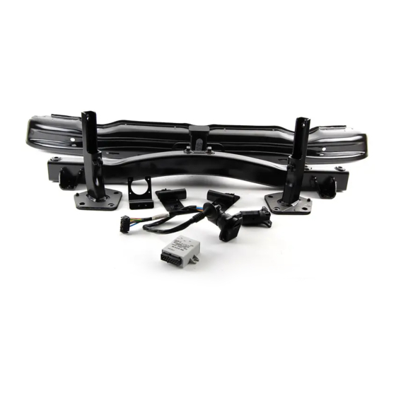
TRAILER HITCH KIT (US Only) - P/N 71 60 0 009 711
MODEL
X5 (E53):
SUGGESTED INSTALLATION TIME:
Total installation time may vary depending on vehicle options and equipment.
The instructions below are developed for BMW vehicles and are not to be compared to any other existing
instructions for vehicles other than BMW. No methods other than those specified in this document are to be used
for installation in BMW vehicles. Left and right are determined from the driver's seat.
Carefully read all instructions and supplements before proceeding with the installation. Reference should be
made to TIS for instructions dealing with a stock part of the vehicle but not stated in detail in these instructions.
The instructions were complete and up to date at time of publication; however, changes to the vehicle or
installation may have occurred. Please report any problems or changes noted with the installation to BMW
Technical Hotline, along with VIN, date of manufacture and as much detail as possible.
Note: BMW NA does not supply or have an approved electrical brake controller for this Trailer
Hitch (Tow Bar) Kit.
DO IT RIGHT THE FIRST TIME, ON TIME, EVERY TIME
Installation Instruction P/N 01 29 2 154 664
2008 BMW of North America, LLC
Select Vehicle Production 10/99 – 8/06
2.5 HOURS**
Page 1 of 13
May 2009
Ver 2.0
Accessory
Development
Advertisement
Table of Contents

Related Manuals for BMW 71 60 0 009 711

Summary of Contents for BMW 71 60 0 009 711
- Page 1 The instructions below are developed for BMW vehicles and are not to be compared to any other existing instructions for vehicles other than BMW. No methods other than those specified in this document are to be used for installation in BMW vehicles. Left and right are determined from the driver’s seat.
- Page 2 PARTS INFORMATION Contents of Kit - P/N 71 60 0 009 711 Ref. Description BMW Part Number Basic tow bar Left support Right support Bumper carrier Bumper bracket Hexagon bolt M10x30 -10.9 Hexagon bolt M10x85 -10.9 Hexagon bolt M10x40 -10.9 Hexagon bolt M10x120 -10.9...
- Page 3 Vehicle Preparation 1. Disconnect battery. 2. Fold up floor cover. 3. Remove spare wheel. 4. Remove luggage compartment trim on right and left side. Reference TIS 51 47 172. 5. Remove luggage compartment trim on rear panel. Reference TIS 51 47 101. 6.
- Page 4 Wiring 1. Remove the spare wheel bracket/air suspension pump (1) by removing the four bolts (2). 2. Remove the plastic electrical box cover plate (1) by removing the three Phillips head screws (2). 3. Remove plastic carrier plate (1) by removing the three Phillips head screws (2 &...
- Page 5 6. Remove plug from hole (1) in rear of body. 7. Secure trailer connector (1) to trailer wiring harness (2). Engage locking tab (3) into connector housing. 8. Route the wiring harness (1) through the hole in the body (2). Install rubber grommet (3) into body.
- Page 6 Crossmember Installation 1. Mount the left and right support (1) through the opening in the body for the metallic impact absorber (a). Repeat this step for both left, and right sides. Note: The support brackets are position specific. The locating pin on each bracket must be in the lower inward position.
- Page 7 5. Install two M10x40 bolts (1) into the basic part of the tow bar (2). Repeat this step for left and right sides. 6. Install two M10x120 bolts (2) into the left and right bumper bracket (1). Position each bumper bracket on the tow bar with the protruding end of the center tube facing down.
- Page 8 10. Secure the trailer harness connector bracket (1) with the M6x16 bolts, and washers (2). 11. Secure 7-pin trailer connector (1) to bracket with four Phillips head screws (2) Installation Instruction P/N 01 29 2 154 664...
- Page 9 Bumper Preparation 1. Remove the bumper carrier from the bumper. (Old bumper carrier is no longer required with the trailer hitch mounted). 2. Secure the supplied bumper carrier to the bumper cover. 3. Reinstall bumper cover/carrier assembly on vehicle. Secure with original Torx screws (1) are now screwed through the tow bar bumper brackets.
- Page 10 6. Apply the adhesive label (white “capacities” label) over the receiver tube on the painted surface of the bumper (clean application area beforehand). 7. Apply the adhesive label (white “no electric brake” label) on the painted surface of the bumper as shown. (clean application area beforehand) Installation Complete Installation Instruction P/N 01 29 2 154 664...
- Page 11 WEIGHT SPECIFICATIONS PLEASE READ ALL OF THE FOLLOWING SPECIFICATIONS BEFORE TRAILERING WITH YOUR X5 (E53) VEHICLE. THE FOLLOWING SPECIFICATIONS APPLY TO ALL X5 (E53) VEHICLES: Maximum towing weight for trailers without brakes (on and off road)………….1650 lbs. Maximum tongue weight for trailers without brakes (on and off road)…………. 330 lbs. Maximum towing weight for trailers with brakes (off road)………………………3300 lbs.
- Page 12 CIRCUIT DIAGRAM Installation Instruction P/N 01 29 2 154 664...
- Page 13 LEGEND Light module Trailer module Fuse holder III Light module A Light module B X318 Tail light right I X319 Tail light left I X393 Car trailer module X494 Earth-VII X498 Earth-VIII X595 VB 58 X609 Trailer module X1232 VB 58R X1986 K530-F205 X10017...
Need help?
Do you have a question about the 71 60 0 009 711 and is the answer not in the manual?
Questions and answers