Table of Contents
Advertisement
Quick Links
Advertisement
Table of Contents

Related Manuals for Bosch ADS?AMC2?2WCF


Summary of Contents for Bosch ADS?AMC2?2WCF
- Page 1 Access Modular Controller 2 ADS‑AMC2‑2WCF | APC‑AMC2‑2WCF Installation manual...
-
Page 3: Table Of Contents
Connecting the power supply to the controller Ethernet Host Interface RS-485 Host Interface Operating Configuring Ethernet interface Troubleshooting Resetting the software Resetting the device to factory default Service and repair Disposal Technical specifications Appendices 10.1 Connecting diagrams Bosch Security Systems B.V. 2019-11 | V02 |... -
Page 4: Controller 2
Warning! Risk of explosion of lithium battery The battery can explode if replaced incorrectly. Replace battery with the same type as recommended by Bosch. Dispose used batteries according to the instructions of the manufacturer of the batteries. Caution! -
Page 5: Unpacking
If any parts are missing, inform your customer service representative or a Bosch Security Systems salesperson. The shipping carton is the safest transport container for the unit. Store it and the other packaging material for future use. If the unit has to be sent back, use the original packaging. -
Page 6: Short Information
Manufacturing dates For product manufacturing dates, go to http:// www.boschsecurity.com/datecodes/ and refer to the serial number on the product label. Remarks This hardware is part of a security system. 2019-11 | V02 | Bosch Security Systems B.V. - Page 7 Bosch Security Systems retains all rights not expressly granted. Nothing in this license constitutes a waiver of Bosch’s rights under the U.S. Copyright laws or any other federal or state law. If you need further assistance or have any questions, contact: Bosch Security Systems B.V.
-
Page 8: Introduction
This guarantees autonomous access decisions and complete access registrations even if the management host system is offline. The built in compact flash card provides adequate storage capability for cardholders and events. 2019-11 | V02 | Bosch Security Systems B.V. - Page 9 Once selected, all the inputs and outputs are predefined. These settings can be changed to choose every free contact of the controller or a connected extension. Bosch Security Systems B.V. 2019-11 | V02 |...
-
Page 10: Product Overview
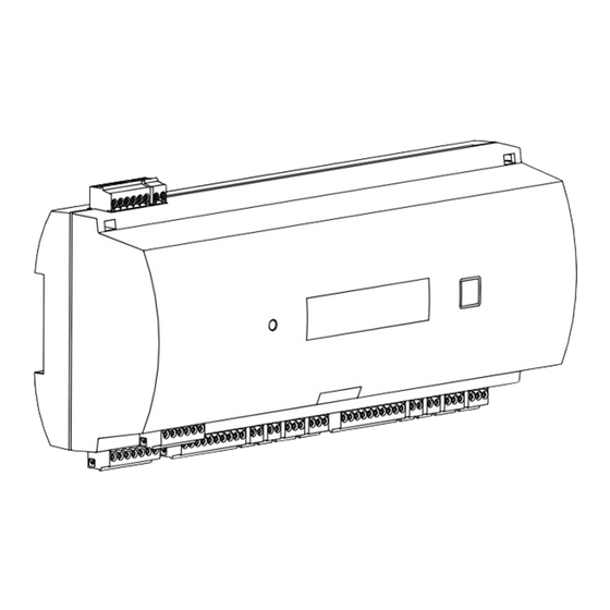
Reset push button - reachable through the casing using a screwdriver Liquid Crystal Display Push button, available on top of the housing, to select different display modes Jumper: Equalization of potential between different systems and earth ground (shield) 2019-11 | V02 | Bosch Security Systems B.V. - Page 11 Figure 3.3: Interfaces - overview 12 RS-485 extension module bus 13 External tamper contact 14 Connector for power supply 15 Wiegand interfaces for card readers 16 Connectors for analog inputs 17 Connectors for relay outputs Bosch Security Systems B.V. 2019-11 | V02 |...
- Page 12 18 Jumper for setting either voltage free relay output (“dry” mode) or looped-in voltage from the AMC internal power supply (“wet” mode). 19 Jumper: Equalization of potential between different systems and earth ground (shield) for the extension interface. 2019-11 | V02 | Bosch Security Systems B.V.
- Page 13 Software versions and date of the firmware - every 5 sec. alternating LBUS or BG900 with the display of the reader interface. S/N1: 0910019212 Bosch serial number S/N2: 00000001 02.06 15:35:15 (S) Current date and time (S) = Summer; (W) = Winter Dig. IO: ::::::::::::::::...
- Page 14 Host activity: + = online - = offline "C" = Counter of the received data packages from the host interface. RS 485 Bus connection: A = Address 1 … H = Address 8 2019-11 | V02 | Bosch Security Systems B.V.
-
Page 15: System Overview
In the communication chain of a system, the access controller is integrated between the host system and the peripheral devices. It is possible to connect up to two readers to the access modular controller. Bosch Security Systems B.V. 2019-11 | V02 |... -
Page 16: Installing
Figure 4.1: Mounting the controller on a mounting rail 2019-11 | V02 | Bosch Security Systems B.V. -
Page 17: Unmounting The Device From A Mounting Rail
Push down the controller until the lower edge snaps out of the mounting rail [1]. Pull the lower end of the controller from the mounting rail [2]. Figure 4.2: Unmounting the controller from a mounting rail Bosch Security Systems B.V. 2019-11 | V02 |... -
Page 18: Opening The Case
The controller’s case consists of a top cover mounted with a two-point snap-in closure on a chassis. To open the case, push down the two snap-ins with a screwdriver, then swing the cover down. Figure 4.3: Opening the controller’s case 2019-11 | V02 | Bosch Security Systems B.V. -
Page 19: Closing The Case
Insert the hooks on the lower edge of the front cover into the lugs on lower edge of the plastic back cover [1]. Please ensure that the BOSCH logo is not upside-down. The upper edge of the front cover now aligns with the two-point snap-in closures on the upper edge of the back cover [2], and may thus be clicked gently into place. -
Page 20: Cabling
Please, calculate the voltage drop by checking the conductor specifications for characteristic resistance values. The voltage drop shall not exceed 2 V. Example: Length = 100 m/328 ft Critical condition! Install the power supply closer to the controller. 2019-11 | V02 | Bosch Security Systems B.V. - Page 21 Controller 2 Notice! These specifications apply to power supply, readers, relay outputs, and extension interface. Regarding inputs, specific voltage-drop values need to be taken into account. Refer to Connecting Analog Input Devices. Bosch Security Systems B.V. 2019-11 | V02 |...
-
Page 22: Grounding And Shielding
If one device is fed power by another, the cable shielding should be applied to both sides. 4.6.1 Grounding for Host Interface A 1: Delivery status A 2: A 3: Figure 4.5: Location of ground jumper RS-485 host interface 2019-11 | V02 | Bosch Security Systems B.V. -
Page 23: Grounding For Extension Interface
JP2 is set at all devices (= A3) 4.6.2 Grounding for Extension Interface B 1: Delivery status B 2: Figure 4.6: Location of ground jumper bottom side Bosch Security Systems B.V. 2019-11 | V02 |... - Page 24 Jumper B connects the internal ground of the controller to the RS-485 ground of the slave interface. Only set jumper B (B2) if the controller powers all other peripheral devices directly connected to it. 2019-11 | V02 | Bosch Security Systems B.V.
-
Page 25: Connecting The Power Supply To The Controller
(APS-PBC-60 or APS-PSU-60). As the battery charging/discharging levels tend to vary, the AMC2 provides information about the battery status every 10 minutes. This feature allows a more reliable battery status information. Bosch Security Systems B.V. 2019-11 | V02 |... -
Page 26: Ethernet Host Interface
You can accelerate this process by running the following command: ipconfig /flushdns This makes the controller immediately available by its name. 2019-11 | V02 | Bosch Security Systems B.V. -
Page 27: Rs-485 Host Interface
A bus system consists of a bus line and/or one or more branch lines. – Cable lengths exceeding 100 m (300 ft) must be installed as bus lines. – Branch lines are branching connections from a bus line. Bosch Security Systems B.V. 2019-11 | V02 |... - Page 28 The cable length of branch lines must not exceed 100 m (330 ft). To use RS-485 mode at the controller, connect the data cables to the pluggable screw connector of the RS-485 host interface. Figure 4.10: RS-485 host interface 2019-11 | V02 | Bosch Security Systems B.V.
-
Page 29: Operating
Use only alphanumeric characters plus the seperator "-" (minus/dash). – Do not use special characters or spaces. – The network name must start with a letter. – The names are not case sensitive. Bosch Security Systems B.V. 2019-11 | V02 |... -
Page 30: Troubleshooting
– DIL switch 5 is controller. set to OFF – Make sure to (BPA protocol configure the is selected). Ethernet interface correctly. Refer to Configuring the Ethernet Interface for instructions. 2019-11 | V02 | Bosch Security Systems B.V. - Page 31 – Check the configuration of the controller. If necessary, delete all configuration data by Resetting the Device to Factory Default. – Reset the controller as described in Resetting the software, page Bosch Security Systems B.V. 2019-11 | V02 |...
-
Page 32: Resetting The Software
Open the upper case of the controller as described in Opening the Case. Set all six DIL switches of the RS-485 selector to ON as shown in the figure below. Press the reset button on the board. 2019-11 | V02 | Bosch Security Systems B.V. - Page 33 IP = [assigned by DHCP server or “0.0.0.0” if not available] – Subnet mask = [assigned by DHCP server or “0.0.0.0” if not available] – Password = no password – Create your password in the IP Config settings of the AMC. Bosch Security Systems B.V. 2019-11 | V02 |...
-
Page 34: Service And Repair
Upon completion of service or repair work on the controller, ask the service technician to perform safety checks to ensure that the controller operates properly. After sales support For more information, visit https://www.boschsecurity.com/xc/ en/support/. 2019-11 | V02 | Bosch Security Systems B.V. -
Page 35: Disposal
This product and/or battery must be discarded separately from household waste. Discard this product according to local laws and regulations, to allow its reuse and/or recycling. This will help in conserving resources, and in protecting human health and the environment. Bosch Security Systems B.V. 2019-11 | V02 |... -
Page 36: Technical Specifications
30 V DC max. (switching voltage) – 1,25 A max. (switching current) @ 30Vdc Inputs 4× 4-State inputs Tamper switch 2-wire Reset button Power – 10 VDC to 30 VDC – 60 VA max. 2019-11 | V02 | Bosch Security Systems B.V. - Page 37 Access Modular Controller Series Hazardous substance table according to SJ/T 11364-2014 PBDE (Pb) (Hg) (Cd) (PBB (PBD Housing & enclosures PCBA Connectors Electronic components Bosch Security Systems B.V. 2019-11 | V02 |...
- Page 38 GB/T 26572 Notice! The voltage drop from the power supply to the controller affects the interfaces of the controller. The total drop must not exceed 2V. 2019-11 | V02 | Bosch Security Systems B.V.
-
Page 39: Appendices
Figure 10.1: Connectors on upper PCB Shield Data RxTx+ (2-wire) Data Rx+ (4-wire) Data RxTx- (2-wire) Data Rx- (4-wire) Ground (PAG) Data Tx+ (4-wire) Data Tx- (4-wire) Tab. 10.1: RS-485 host on upper PCB Bosch Security Systems B.V. 2019-11 | V02 |... - Page 40 Access Modular en | Appendices Controller 2 TXD+ TXD- RXD+ Not connected Not connected RXD- Not connected Not connected Tab. 10.2: Ethernet Network socket (RJ45) Figure 10.2: Interconnect diagram of the RS-232 serial interface 2019-11 | V02 | Bosch Security Systems B.V.
- Page 41 Analog Input 2 Relay Output 1 AMC2 2W Relay Output 2 Reader Interface 2 Analog Input 3 Analog Input 4 Relay Output 3 Relay Output 4 Figure 10.3: Connector blocks of the AMC2-2W Bosch Security Systems B.V. 2019-11 | V02 |...
- Page 42 Data 1 drain Shield orange green LED brown red LED yellow Beeper blue Hold violet Card Present Tab. 10.4: Wiegand interface AMC Notice! For reader settings refer to the respective reader manual. 2019-11 | V02 | Bosch Security Systems B.V.
- Page 43 Power supply for external devices (10V - 30V) Power supply for external devices (0V) Shield Data RxTx+ Data RxTx- Ground (PAG) Tab. 10.7: Host / Extension interface Tamper Contact, in Tamper Contact, out Tab. 10.8: External tamper contact Bosch Security Systems B.V. 2019-11 | V02 |...
- Page 44 Access Modular | Appendices Controller 2 2019-11 | V02 | Bosch Security Systems B.V.
- Page 45 Access Modular Appendices | Controller 2 Bosch Security Systems B.V. 2019-11 | V02 |...
- Page 46 Access Modular | Appendices Controller 2 2019-11 | V02 | Bosch Security Systems B.V.
- Page 48 Bosch Security Systems B.V. Torenallee 49 5617 BA Eindhoven Netherlands www.boschsecurity.com © Bosch Security Systems B.V., 2019...
Need help?
Do you have a question about the ADS?AMC2?2WCF and is the answer not in the manual?
Questions and answers