Table of Contents
Advertisement
Quick Links
Advertisement
Table of Contents

Subscribe to Our Youtube Channel
Related Manuals for Planet Networking & Communication UPOE-800G


Summary of Contents for Planet Networking & Communication UPOE-800G
- Page 1 User’s Manual of UPOE-800G / UPOE-1600G...
- Page 2 User’s Manual of UPOE-800G / UPOE-1600G Trademarks Copyright © PLANET Technology Corp. 2016. Contents are subject to revision without prior notice. PLANET is a registered trademark of PLANET Technology Corp. All other trademarks belong to their respective owners. Disclaimer PLANET Technology does not warrant that the hardware will work properly in all environments and applications, and makes no warranty and representation, either implied or expressed, with respect to the quality, performance, merchantability, or fitness for a particular purpose.
-
Page 3: Table Of Contents
User’s Manual of UPOE-800G / UPOE-1600G TABLE OF CONTENTS 1. INTRODUCTION ..................5 1.1 P .....................5 ACKAGE ONTENTS 1.2 P ....................6 RODUCT ESCRIPTION 1.3 H ..................11 OW TO ANUAL 1.4 P ....................12 RODUCT EATURES 1.5 P ...................14 RODUCT PECIFICATIONS ... - Page 4 User’s Manual of UPOE-800G / UPOE-1600G 4.3.10 Logout ......................41 4.4 SNMP ........................43 4.4.1 SNMP Management ..................43 4.5 P ....................45 OWER OVER THERNET 4.5.1 PoE Configuration ....................46 4.5.2 PoE Schedule Profile..................48 4.5.3 PoE Alive Check Configuration ................52 4.5.4 PoE Status .......................54 ...
-
Page 5: Introduction
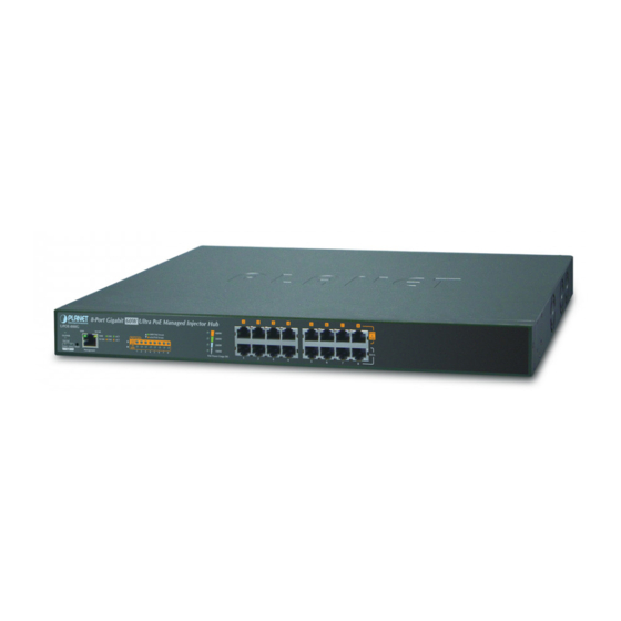
User’s Manual of UPOE-800G / UPOE-1600G 1 . I N TROD UCTI ON Thank you for purchasing PLANET 8-/16-Port Gigabit 60W Ultra PoE Managed Injector Hub, UPOE-800G/UPOE-1600G. The description of this model is shown below: 8-Port Gigabit 60W Ultra PoE Managed Injector Hub (400 watts) -
Page 6: Product Description
User’s Manual of UPOE-800G / UPOE-1600G 1.2 Product Description PLANET Ultra PoE Managed Injector Hub series, a cost-effective and quick Ultra PoE solution, is designed to perfectly upgrade an existing network infrastructure to Ultra Power over Ethernet network system without replacing the existing Ethernet Switch. - Page 7 User’s Manual of UPOE-800G / UPOE-1600G device. It possesses double amount of power capability than the conventional 802.3at PoE and is an ideal solution to satisfying the growing demand for higher power consuming network PDs, such as: ■ PoE PTZ speed dome ■...
- Page 8 User’s Manual of UPOE-800G / UPOE-1600G Built-in Unique PoE Functions for Powered Device Management As it is the Ultra PoE Managed Injector Hub for VoIP, wireless and surveillance networks, the Ultra PoE Managed Injector Hub features the following special PoE management functions: ...
- Page 9 User’s Manual of UPOE-800G / UPOE-1600G Advanced PoE Power Output Mode Management To fulfill the demand of various powered devices consuming stable PoE power, the Ultra PoE Managed Injector Hub provides three different PoE power output modes for selection. ...
- Page 10 The Ultra PoE Managed Injector Hub helps users to monitor the current status of PoE power usage easily and efficiently by its advanced LED indication. The front panel of the UPOE-800G has four green LEDs indicating 100W, 200W, 300W and 400W of PoE power usage.
-
Page 11: How To Use This Manual
User’s Manual of UPOE-800G / UPOE-1600G Smart Fan Design for Silent Operation The Ultra PoE Managed Injector Hub features a low noise design and an effective ventilation system. It supports the smart fan technology that automatically controls the speed of the built-in fan to reduce noise and maintain the temperature of the Ultra PoE Managed Injector Hub for optimal power output capability. -
Page 12: Product Features
Up to 60 watts of power on 4-pair UTP Backward compatible with IEEE 802.3at/af PD device 54V DC, 60-watt PoE power output at maximum on each port, 400-watt PoE budget (UPOE-800G) 52V DC, 60-watt PoE power output at maximum on each port, 600-watt PoE budget (UPOE-1600G) ... - Page 13 User’s Manual of UPOE-800G / UPOE-1600G Management Web interface for remote management Supports Network Time Protocol (NTP) Firmware upgrade through Web interface PLANET Smart Discovery utility automatically finds PLANET devices on the network SNMP trap for alarm notification of events ...
-
Page 14: Product Specifications
User’s Manual of UPOE-800G / UPOE-1600G 1.5 Product Specifications Product UPOE-800G UPOE-1600G Hardware “Data” Input Ports 8 x RJ45 16 x RJ45 Interface “Data + Power” Output Ports 8 x RJ45 16 x RJ45 Management Port 1 x RJ45; 10/100/1000BASE-T, auto-negotiation, auto-MDI/MDIX... - Page 15 User’s Manual of UPOE-800G / UPOE-1600G Management Web, PLANET Smart Discovery Lite Management Interface Power limit by consumption and allocation PoE admin mode Per port power schedule Per port power enable/disable Power feeding priority PoE Management Over temperature protection Current per port usage and status...
-
Page 16: Installation
User’s Manual of UPOE-800G / UPOE-1600G 2 . I N STALLATI ON This section describes the hardware features and installation of Ultra PoE Managed Injector Hub on the desktop or rack mount. For easier management and control of the Ultra PoE Managed Injector Hub, familiarize yourself with its display indicators, and ports. -
Page 17: Led Indicators
User’s Manual of UPOE-800G / UPOE-1600G The following is the summary table of reset button functions: Reset Button Pressed and Released Function About 5 second Reboot the Ultra PoE Managed Injector Hub. Reset the Ultra PoE Managed Injector Hub to Factory Default configuration. -
Page 18: Injector Rear Panel
User’s Manual of UPOE-800G / UPOE-1600G UPOE-1600G ■ System Color Function SYS Power Green Lights to indicate power on. Lights to indicate PoE module failure. PoE Fail FAN1 Fail Lights to indicate FAN1 stops. FAN2 Fail Lights to indicate FAN2 stops. -
Page 19: Installing The Ultra Poe Managed Injector Hub
User’s Manual of UPOE-800G / UPOE-1600G 2.2 Installing the Ultra PoE Managed Injector Hub This section describes how to install your Ultra PoE Managed Injector Hub and make connections to the Ultra PoE Managed Injector Hub. Please read the following topics and perform the procedures in the order being presented. PLANET Ultra PoE Managed Injector Hub does not need software configuration. -
Page 20: Rack Mounting
User’s Manual of UPOE-800G / UPOE-1600G Step 5: Supplying Power to the Ultra PoE Managed Injector Hub. Connect one end of the power cable to the Ultra PoE Managed Injector Hub. Connect the power plug of the power cable to a standard wall outlet. - Page 21 User’s Manual of UPOE-800G / UPOE-1600G Figure 2-2-3: Mounting the Ultra PoE Managed Injector Hub in a Rack Step 6: Proceed with steps 4 and 5 of session 2.2.1 Desktop Installation to connect the network cabling and supply power to your Ultra PoE Managed Injector Hub.
-
Page 22: Network Application Installation
User’s Manual of UPOE-800G / UPOE-1600G 2.2.3 Network Application Installation The Ultra PoE Managed Injector Hub is not an equipment with data switching function between data ports. To inject PoE power and transmit data packets to PDs, the Ultra PoE Managed Injector Hub is usually linked to an Ethernet switch. -
Page 23: Power Over Ethernet Powered Device
Since the Ultra PoE Managed Injector Hub per PoE port supports 52V (UPOE-1600G) or 54V DC (UPOE-800G) PoE power output, please check and assure the Powered Device’s (PD) acceptable DC power is 52V (UPOE-1600G) and 54V DC (UPOE-800G); otherwise, it will damage the Powered Device (PD). -
Page 24: Management
User’s Manual of UPOE-800G / UPOE-1600G 3 M AN AGEM EN T This chapter describes how to manage the Ultra PoE Managed Injector Hub with the following topics included: - Overview - Management Method - Logging on to the Ultra PoE Managed Injector Hub 3.1 Overview... -
Page 25: Management Method
User’s Manual of UPOE-800G / UPOE-1600G 3.3 Management Method User can manage the Ultra PoE Managed Injector Hub by Web Management via a network connection. 3.3.1 Web Management The Ultra PoE Managed Injector Hub can be configured through an Ethernet connection. The factory default IP address is 192.168.0.100 with subnet mask 255.255.255.0, so please make sure the manager PC must be set to the same IP subnet... -
Page 26: Planet Smart Discovery Utility
User’s Manual of UPOE-800G / UPOE-1600G 1. For security reason, please change and memorize the new password after this first setup. 2. Only accept command in lowercase letter under Web interface. 3.3.2 PLANET Smart Discovery Utility For easily listing the Ultra PoE Managed Injector Hub in your Ethernet environment, Planet Smart Discovery Utility from user’s manual CD-ROM is an ideal solution. - Page 27 User’s Manual of UPOE-800G / UPOE-1600G Press the “Refresh” button for the currently-connected devices in the discovery list and the screen is shown as follows: Figure 3-1-4: Planet Smart Discovery Utility Screen This utility shows all necessary information from the devices, such as MAC address, device name, firmware version and device IP subnet address.
-
Page 28: Web Configuration
Ultra PoE Managed Injector Hub from the local LAN. This section indicates how to configure the Ultra PoE Managed Injector Hub to enable its smart function. The following web screen is based on the UPOE-1600G. The display of the UPOE-800G is the same as that of the UPOE-1600G. -
Page 29: Web Panel
User’s Manual of UPOE-800G / UPOE-1600G 4.2 Web Panel At the top of the Web management page, the active panel displays the link status of management port and PoE ports. Figure 4-2-1: Web Panel Screen Green light indicates network data is sending or receiving. -
Page 30: System Information
User’s Manual of UPOE-800G / UPOE-1600G Firmware Upgrade Allow to upgrade the latest firmware in the future. Explained in section 4.3.5. Configuration Setting Allow to back up or restore system configuration. Explained in section 4.3.6. Factory Default Allow to reset system to factory default setting. -
Page 31: Ip Configuration
User’s Manual of UPOE-800G / UPOE-1600G 4.3.2 IP Configuration This section provides the IP Configuration of Ultra PoE Managed Injector Hub as the screen in Figure 4-3-2 appears. Table 4-3-2 describes the IP Configuration object of Ultra PoE Managed Injector Hub. -
Page 32: Ntp Configuration
User’s Manual of UPOE-800G / UPOE-1600G 4.3.3 NTP Configuration This section provides the NTP Configuration of Ultra PoE Managed Injector Hub as the screen in Figure 4-3-3 appears and Table 4-3-3 describes the NTP Configuration object of Ultra PoE Managed Injector Hub. -
Page 33: Password Setting
User’s Manual of UPOE-800G / UPOE-1600G 4.3.4 Password Setting This section provides the Password Setting of Ultra PoE Managed Injector Hub as the screen in Figure 4-3-4 appears. Table 4-3-4 describes the Password Setting objects of Ultra PoE Managed Injector Hub. -
Page 34: Firmware Upgrade
User’s Manual of UPOE-800G / UPOE-1600G 4.3.5 Firmware Upgrade This section provides the firmware upgrade of Ultra PoE Managed Injector Hub as the screen in Figure 4-3-5 appears. Figure 4-3-5: Firmware Upgrade Web Page Screen Please press “Browse” to locate the latest firmware of Ultra PoE Managed Injector Hub that deposits in your PC. The... -
Page 35: Configuration Setting
User’s Manual of UPOE-800G / UPOE-1600G 4.3.6 Configuration Setting This function allows output the current Ultra PoE Managed Injector Hub configuration as a file, and upload it to other Ultra PoE Managed Injector Hub for quick multi-devices setting. The description of the procedure and screens in the following appears. - Page 36 User’s Manual of UPOE-800G / UPOE-1600G Figure 4-3-10: File Save Screen Configuration Upload ■ Click the “Browse” button of the Configuration Setting Web page and the system would pop up the file selection screen to choose saved configuration. The screen in Figure 4-3-11 appears.
-
Page 37: Factory Default
User’s Manual of UPOE-800G / UPOE-1600G Select on the configuration file and then click “Upload”. After system has uploaded, the screen in Figure 4-3-12 appears. Figure 4-3-12: Configuration Upload Finished Screen When configuration has been uploaded, please re-login the system. - Page 38 User’s Manual of UPOE-800G / UPOE-1600G Please press the “Reset” button to take effect and the “Do you really want to reset the current settings to default?” popup window appears. Please press the “OK” button to continue the factory default process. The screen appears in Figure 4-3-15.
-
Page 39: System Log
User’s Manual of UPOE-800G / UPOE-1600G 4.3.8 System Log This section provides the system log setting and information display of Ultra PoE Managed Injector Hub as the screen in Figure 4-3-18 appears. Table 4-3-6 describes the system log setting object of Ultra PoE Managed Injector Hub. -
Page 40: System Reboot
User’s Manual of UPOE-800G / UPOE-1600G 4.3.9 System Reboot This section provides the system reboot function of Ultra PoE Managed Injector Hub as the screen in Figure 4-3-19 appears. Figure 4-3-19: System Reboot Web Page Screen Press the “Reboot” button to reboot the Ultra PoE Managed Injector Hub as the screen in... -
Page 41: Logout
User’s Manual of UPOE-800G / UPOE-1600G 4.3.10 Logout This section provides logout function of Ultra PoE Managed Injector Hub as the screen in Figure 4-3-21 appears. Figure 4-3-21: Logout Web Page Screen Press the “Logout” button and then the popup window with re-login request appears as the screen in Figure 4-3-22 appears. - Page 42 User’s Manual of UPOE-800G / UPOE-1600G Figure 4-3-23: Main Web Page Screen...
-
Page 43: Snmp
User’s Manual of UPOE-800G / UPOE-1600G 4.4 SNMP The Simple Network Management Protocol (SNMP) is an application layer protocol that facilitates the exchange of management information between network devices. It is part of the Transmission Control Protocol/Internet Protocol (TCP/IP) protocol suit. SNMP enables network administrations to manage network performance, find and solve network problems, and plan for network growth. - Page 44 User’s Manual of UPOE-800G / UPOE-1600G Object Description SNMP Agent Disable or enable the SNMP Agent function of Ultra PoE Managed Injector Hub. Allow to input characters for SNMP Read Community of Ultra PoE Managed SNMP Read Community Injector Hub.
-
Page 45: Power Over Ethernet
User’s Manual of UPOE-800G / UPOE-1600G 4.5 Power over Ethernet Power Management: In a Power over Ethernet system, operating power is applied from a power source (PSU-power supply unit) over the LAN infrastructure to powered devices (PDs), which are connected to ports. Under some conditions, the total output power required by PDs can exceed the maximum available power provided by the PSU. -
Page 46: Poe Configuration
User’s Manual of UPOE-800G / UPOE-1600G 4.5.1 PoE Configuration This section provides PoE (Power over Ethernet) Configuration and PoE output status of Ultra PoE Managed Injector Hub as screen in Figure 4-5-2 appears. Table 4-5-2 describes the PoE Configuration object of Ultra PoE Managed Injector Hub. - Page 47 User’s Manual of UPOE-800G / UPOE-1600G This function provides input per port description and the available letters is 30. Description NOTE: The total maximum letters are only 800. Some of special words will count as 5 per word, like ‘, “, \, < and >.
-
Page 48: Poe Schedule Profile
User’s Manual of UPOE-800G / UPOE-1600G 4.5.2 PoE Schedule Profile This section provides user to configure PoE schedule and scheduled power recycling. The “PoE schedule” helps you to enable or disable PoE power feeding for PoE ports during specified time intervals and it is a powerful function to help SMBs or enterprises save power and money. - Page 49 User’s Manual of UPOE-800G / UPOE-1600G The PoE Schedule Profile Web Screens are shown in Figure 4-5-3 Table 4-5-3. Figure 4-5-3: PoE Configuration Web Page Screen The page includes the following information: Object Description Allows user to disable or enable per port PoE function, also allow choose ...
- Page 50 User’s Manual of UPOE-800G / UPOE-1600G PoE Schedule user can configure a duration time for PoE port as default value does not provide power; screen in Figure 4-5-4 Table 4-5-4 show. Figure 4-5-4: PoE Schedule Web Page Screen The page includes the following information:...
- Page 51 User’s Manual of UPOE-800G / UPOE-1600G Start Hour Allows user to set what hour PoE function does by enabling it. Start Min Allows user to set what minute PoE function does by enabling it. End Hour Allows user to set what hour PoE function does by disabling it.
-
Page 52: Poe Alive Check Configuration
User’s Manual of UPOE-800G / UPOE-1600G 4.5.3 PoE Alive Check Configuration The Ultra PoE Managed Injector Hub can be configured to monitor connected PD’s status in real-time via ping action. Once the PD stops working and without response, the Ultra PoE Managed Injector Hub are going to restart PoE port power, and bring the PD back to work. - Page 53 User’s Manual of UPOE-800G / UPOE-1600G The page includes the following fields: Object Description Mode Allows user to enable or disable per port PD Alive Check function. All ports are disabled as default value. Remote PD IP Address This column allows user to set PoE device IP address here for system making ping to the PoE device.
-
Page 54: Poe Status
User’s Manual of UPOE-800G / UPOE-1600G 4.5.4 PoE Status This page allows user to see the usage of individual PoE Port. The screen in Figure 4-5-6 appears Figure 4-5-6: PoE Status Screenshot The page includes the following fields: Object Description ... -
Page 55: Power Over Ethernet Overview
User’s Manual of UPOE-800G / UPOE-1600G 5 . POW ER OVER ETH ERN ET OVERVI EW What is PoE? Based on the global standard IEEE 802.3af, PoE is a technology for wired Ethernet, the most widely installed local area network technology adopted today. PoE allows the electrical power necessary for the operation of each end-device to be carried by data cables rather than by separate power cords. - Page 56 User’s Manual of UPOE-800G / UPOE-1600G Figure 5-1-1 - Power Supplied over the Spare Pins The data pairs are used. Since Ethernet pairs are transformer coupled at each end, it is possible to apply DC power to the center tap of the isolation transformer without upsetting the data transfer. In this mode of operation the pair on pins 3 and 6 and the pair on pins 1 and 2 can be of either polarity.
-
Page 57: The Poe Provision Process
User’s Manual of UPOE-800G / UPOE-1600G 6 . TH E POE PROVI SI ON PROCESS While adding PoE support to networked devices is relatively painless, it should be realized that power cannot simply be transferred over existing Cat5e cables. Without proper preparation, doing so may result in damage to devices that are not designed to support provision of power over their network interfaces. -
Page 58: Start-Up
User’s Manual of UPOE-800G / UPOE-1600G Classifying a PD according to its power consumption may assist a PoE system in optimizing its power distribution. Such a system typically suffers from lack of power resources, so that efficient power management based on classification results may reduce total system costs. - Page 59 User’s Manual of UPOE-800G / UPOE-1600G AC Disconnect detection involves the induction of low AC signal in addition to the 52 VDC operating voltage. The returned AC signal amplitude is monitored by the PSE at the port terminals. During normal operation, the PD's relatively low impedance lowers the returned AC signal while a sudden disconnection of this PD will cause a surge to the full AC signal level and will indicate PD disconnection.
-
Page 60: Mdi Settings
User’s Manual of UPOE-800G / UPOE-1600G APPEN D I X A A.1 MDI Settings The Medium-Dependent Interface (MDI or RJ45) serves as the data/power interface between Ethernet elements. As such, it has two optional connection methods to carry the power. Named Alternative A & B, Table 1 details the two power feeding alternatives. -
Page 61: Data Out Poe Injector Rj45 Port Pin Assignments
User’s Manual of UPOE-800G / UPOE-1600G A.3 DATA OUT PoE Injector RJ45 Port Pin Assignments PIN NO 10BASE-T 1000BASE-T 100BASE-TX A.4 RJ45 Pin Assignment of Non-802.3af/802.3at Standard PD with PoE Mid-span PD Pin out of Cisco non-802.3af standard PD Pin out of POE Mid-span...
Need help?
Do you have a question about the UPOE-800G and is the answer not in the manual?
Questions and answers