Table of Contents
Advertisement
Quick Links
Advertisement
Table of Contents

Related Manuals for Hoffer Flow Controls CAT1 Series

Summary of Contents for Hoffer Flow Controls CAT1 Series
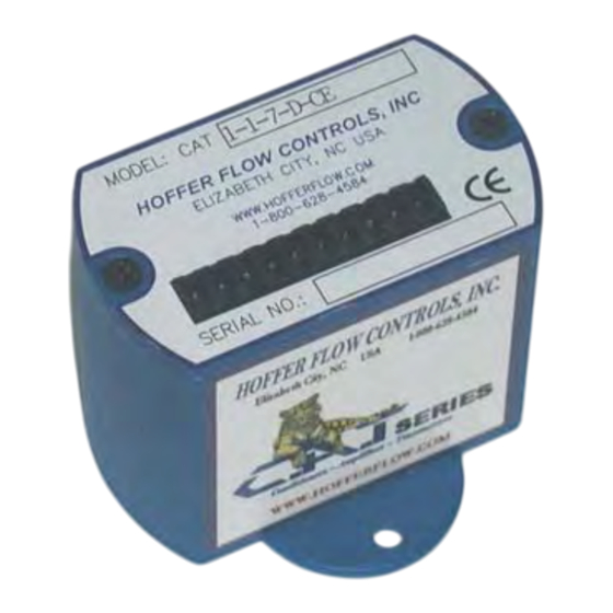
- Page 1 Microprocessor Controlled Two-Wire 4-20mA Loop Powered Transmitter Model: CAT1 USER’S MANUAL HP-310 HP-310 April 2009 February 2008 107 Kitty Hawk Lane, P.O. Box 2145, Elizabeth City, NC 27906-2145 800-628-4584 252-331-1997 FAX 252-331-2886 www.hofferflow.com E-mail: info@hofferflow.com...
- Page 3 RETURN REQUESTS/INQUIRIES Direct all warranty and repair requests/inquiries to the Hoffer Flow Controls Customer Service Department, telephone number (252) 331-1997 or 1-800-628-4584. BEFORE RETURNING ANY PRODUCT(S) TO HOFFER FLOW CONTROLS, PURCHASER MUST OBTAIN A RETURNED MATERIAL AUTHORIZATION (RMS) NUMBER FROM HOFFER FLOW CONTROLS’...
- Page 4 LIMITED WARRANTY HOFFER FLOW CONTROLS, INC. (“HFC”) warrants HFC’s products (“goods”) described in the specifications incorporated in this manual to be free from defects in material and workmanship under normal use and service, but only if such goods have been properly selected for the service intended, properly installed and properly operated and maintained.
-
Page 5: Table Of Contents
CONTENTS Introduction ------------------------------------------------------------ 1 Model Number Designation ------------------------------------- 2 Specifications----------------------------------------------------------- 5 Principle of Operation ----------------------------------------------- 7 Functional Blocks ------------------------------------------------- 7 3-1-1 Preamplifier -------------------------------------------------- 7 3-1-2 Microcontroller ---------------------------------------------- 8 3-1-3 Loop Driver -------------------------------------------------- 8 3-1-4 Communications Interface --------------------------------- 8 System Response Time------------------------------------------- 9 Installation------------------------------------------------------------- 11 Typical Connections --------------------------------------------- 11 Communications Connections---------------------------------- 12... -
Page 7: Introduction
Introduction 1. Introduction The CAT1 is a microprocessor based loop powered transmitter. The transmitter accepts a low-level frequency signal on the input and provides a 4-20mA analog output proportional to the flow rate. CAT1 is compatible with all Hoffer turbine flowmeters as well as the H.O.G. series positive displacement flowmeters. -
Page 8: Model Number Designation
Introduction Model Number Designation MODEL CAT1-( ENCLOSURE STYLE LINEARIZED ANALOG OUTPUT INPUT POWER SPECIAL FEATURES ENCLOSURE STYLE MODEL CAT1-( ( A ) OPTION GENERAL PURPOSE. 2.6"L X 2.6"H X 2.6"W MINIMUM MOUNTING SPACE. 2" LONG DIN RAIL MOUNT SINGLE UNIT. UP TO 20 CAT1 UNITS CAN BE MOUNTED ON A SINGLE RAIL. - Page 9 Introduction LINEARIZED ANALOG OUTPUT MODEL CAT1-( )-( ( B ) OPTION 4 TO 20 MA UP TO 20 POINTS. ACCURACY +/-0.02% OF FULL SCALE. INPUT POWER MODEL CAT1-( ( C ) OPTION 8 TO 24 VDC LOOP POWERED. SPECIAL FEATURES MODEL CAT1-( ( D ) OPTION...
- Page 10 Introduction This page intentionally left blank. HP-310...
-
Page 11: Specifications
Specifications 2. Specifications Specifications Input Signal Type: Magnetic pick up, Contact Closure Input frequency range: 0.2 Hz to 4 KHz Signal level: 10 mV rms to 30 Vdc Power supply: Loop Power 8-30 Vdc Reverse polarity protection Analog Output: 4-20 mA 24 mA overflow condition Load resistance: Max 650 Ohms at 24 Vdc... - Page 12 Specifications This page intentionally left blank. HP-310...
-
Page 13: Principle Of Operation
Principle of Operation 3. Principle of Operation The CAT1 consists of two printed circuit boards and four main functional blocks: the Preamplifier, Microcontroller, Loop Driver, and Communications Interface. PCA183 PCA180 MICROCONTROLLER CONDITIONED SIGNAL FLOWMETER INPUT PREAMP COMMUNICATIONS LOOP INTERFACE 4-20 mA 4-20 mA DRIVER RS232... -
Page 14: Microcontroller
Principle of Operation 3-1-2 Microcontroller The Microcontroller, located on PCA183, accepts the square-wave output of the preamplifier and performs all of the calculations that are required to control the Loop Driver. After measuring the frequency of the square-wave, the Microcontroller uses the following equations to compute the flow rate and current. -
Page 15: System Response Time
Principle of Operation System Response Time The analog output response time to reach steady state due to a change in the flow rate is approximately (1/8) seconds. When flow stops, the time for the analog output to return to 4 mA will be between 3 and 12 seconds, depending on the Maximum Sample Time (MST) setting. - Page 16 Principle of Operation This page intentionally left blank. HP-310...
-
Page 17: Installation
Installation 4. Installation NOTE: CAT1 flow input interfaces with magnetic type pickup coils and contact closure only. If another type of coil is required, refer to CAT 2 and CAT3 models. Typical Connections Loop powered with MAG Coil Installation POWER SUPPLY SIG+ SIG-... -
Page 18: Communications Connections
Installation Communications Connections The RS232 serial port connector is located under the top plate of CAT1 and may be accessed by removing the two screws from the top plate. A matching connector is provided with HOFFER HIT2A-301 Communications Cable. CAT1 unit has to be powered from external supply in order to be able to communicate. -
Page 19: Appendix A - Default Configuration
Appendix A – Default Configuration Appendix A – Default Configuration Factory default configuration: FIELD Value 10000000 0 (Average) 1.00 4999.981 4999.982 4999.983 4999.984 4999.985 4999.986 4999.987 4999.988 4999.989 4999.990 4999.991 4999.992 4999.993 4999.994 4999.995 4999.996 4999.997 4999.998 4999.999 5000.000 1.00 1.00 1.00 1.00... - Page 20 Appendix A – Default Configuration FIELD Value 1.00 1.00 1.00 1.00 1.00 100 (GAL) 1 (MIN) 1234 0 (Rate) HP-310...
-
Page 21: Appendix B - Communications
– Appendix B Communications 15 Appendix B – Communications Message Format And Timeout Communication messages consist of a string of ASCII characters terminated by a carriage return character. The maximum message length received by CAT1 is 20 characters, including the carriage return. The CAT1 will transmit no more than 35 characters before transmitting a carriage return. - Page 22 Appendix B – Communications READ Example: If the sending unit wishes to read the number of points that the CAT1 has in the K factor table, the sending unit shall send “NP<CR>” The CAT1 echoes the sent message, and responds with “NUM PTS 2<CR>”...
-
Page 23: Messages
– Appendix B Communications 17 Messages Commands Supported By Communications Messages Command Description/Allowed Data/Response Tag Number “0” to “99999999” “TAG NUM = (DATA)” The first three digits are the units code for total. Changing these digits will change the TU settings. Linearization “0”... - Page 24 Appendix B – Communications Command Description/Allowed Data/Response Frequency 1-20 F01 has a range of “0.000” to the value of F02 minus 0.001; F20 has a range of the value from F19 plus 0.001 to “5000.000”; Frequencies F02 to F19 must be 0.001 greater than the previous frequency and 0.001 less than the next frequency.
- Page 25 – Appendix B Communications 19 Command Description/Allowed Data/Response Rate Units “0” for seconds “1” for minutes “2” for hours “3” for days “FLOW UNITS=(DATA)” (DATA) shall be: “SEC” for seconds “MIN” for minutes “HR ” for hours “DAY” for days Max Sample Time “1”...
- Page 26 Appendix B – Communications System Commands Supported by Communications Messages System Description/Response/Comments Command Output 4mA “ Output is 4mA.” Current output set to 4mA. Output 12mA “ Output is 12mA.” Current output set to 12mA. Output 20mA “ Output is 20mA.” Current output set to 20mA.
- Page 27 – Appendix B Communications 21 System Description/Response/Comments Command Read Rate “FLOW = (DATA)” (DATA) = “0” to the following maximums: “99999.999” if RD = 3 “999999.99” if RD = 2 “9999999.9” if RD = 1 “ 99999999” if RD = 0 Adjust 4mA output point “CN=#(DATA)”...
Need help?
Do you have a question about the CAT1 Series and is the answer not in the manual?
Questions and answers