Advertisement
333 Bayview Avenue, Amityville, New York 11701
For Sales and Repairs, (800) 645-9445
For Technical Service, (800) 645-9440 or visit us at
http://tech.napcosecurity.com/
(Note: Technical Service is for security professionals only)
Publicly traded on NASDAQ
Symbol: NSSC
© NAPCO 2018
INTRODUCTION
The SLE-LTEVI-FIRE Dual-Path Alarm Communicator is
specifically designed to interface with FACP (Fire Alarm
Control Panels) and to comply with UL 864. The SLE-
LTEVI-FIRE is equipped with two dry relays, one for a
trouble output and one for an auxiliary output. The unit is
also equipped with four supervised inputs to report a Fire
Alarm, a Fire Trouble, a Water Flow Alarm and a Supervi-
sory Alarm, each triggered from the N/O and Common ter-
minals of the associated FACP output relays.
When connected to a FACP with one or two standard RJ-
45 telephone inputs, the SLE-LTEVI-FIRE provides two
RJ-45 outputs to satisfy both telephone inputs. The prima-
ry RJ-45 output is supervised and reports a trouble to the
central station upon any open or short on the primary RJ-
45 wires that prevent reporting. The secondary telephone
line is supervised by the FACP; when a line fault is detect-
ed, a trouble is reported to the central station through the
primary telephone line.
When connected to a FACP without digital dialing capabil-
™
ity, the StarLink
SLE-LTEVI-FIRE Dual-Path Commercial
Fire alarm capture radio communicator is a fully super-
vised, wireless digital two-way subscriber unit supported by
an extensive nationwide wireless network.
LTEVI-FIRE is compatible with most 12 or 24VDC alarm
control panels (always adhere to the documentation provid-
ed by the control panel manufacturer). Mount the unit to a
single-, dual-, or three-gang electrical box and route the
wires through the back knockout(s), or as specified by local
codes. See WI2140 for programming information.
The SLE-LTEVI-FIRE communicator uses proprietary
data-capture technology that captures the alarm report
from the control panel and transmits the alarm signals to
the SLE Control Center; the alarm signals are then for-
warded to ANY central station via Contact ID or 4/2 via
DACT from the NOC or Sur-Gard System II, Sur-Gard Sys-
tem V, Bosch D6100IPV6 or Bosch D6600 Receiver (with
ITS-D6686 Ethernet Adapter) via TCP/IP using standard
line security. The SLE Control Center reports a trouble
signal in the event that the network does not receive the
expected supervision signal from the wireless communica-
tor. In addition, the SLE-LTEVI-FIRE is powered directly
from the control panel.
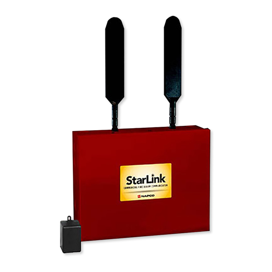
SLE-LTEVI-FIRE - Commercial / Residential Fire LTE Veri-
zon Network Compatible GSM alarm capture Communi-
cator. SIM card included. Red plastic enclosure. Rated
nominal 12/24VDC input.
*For Commercial Fire installations, a UL Listed Fire Alarm regulated power
supply or FACP regulated auxiliary output is required.
™
StarLink
SLE-LTEVI-FIRE Commercial Series Dual-Path Alarm Communicator -- Installation Instructions
StarLink™
Commercial SLE-LTEVI-FIRE
Dual-Path Alarm Communicator
INSTALLATION INSTRUCTIONS
The SLE-
ADDITIONAL COMPONENTS
In addition to the SLE-LTEVI-FIRE listed above, the fol-
lowing sub-assemblies are available:
SLE-WIFI-MODULE - Allows your Napco StarLink
to connect to the Internet by means of a wireless (Wi-Fi)
link, eliminating a wired Ethernet cable connection.
Note: 7AH battery required when using the SLE-
WIFI-MODULE. For more information, see WI2191.
SLE-DLCBL - Download Cable, 6 feet.
SLE-ANTEXT30 - Extended antenna with 30 feet of cable
SLE-ANTEXT50 - Extended antenna with 50 feet of cable
SLE-ANTEXT75 - Extended antenna with 75 feet of cable
(Any suitable external cellular antenna is permitted by
UL). Always follow the manufacturer's installation in-
structions. Note: Antennas are not Listed by UL. For
LTE radios where an External Antenna needs to be in-
stalled outside of the room in which the radio is installed
(maximum 30 meters (98 feet) in Residential applica-
tions),
please
9SLELTEEXAPSLD available from our Customer Ser-
vice
Department,
9SLELTEEXAPSLD is identified by "two red dots" locat-
ed on the lower right corner of the board. See WI2239
included with the 9SLELTEEXAPSLD for the simple in-
stallation procedure.
SPECIFICATIONS
Electrical Ratings for +12V / 24V (powered by the con-
trol panel)*
Input Voltage: 10-25VDC regulated (power-limited out-
put from Listed control panel).
Input Current:
10VDC standby: 162mA
12VDC standby: 125mA
15VDC standby: 110mA
24VDC standby: 100mA
25VDC standby: 100mA
Wi-Fi Module: (Optional) Add 40mA to the above.
(With peak RF transmission current of 300mA).
Electrical Ratings for the IN 1 Fire Input:
Input Voltage: 9-25VDC.
Maximum Input Current: Up to 2mA from FACP NAC
circuit
AGENCY LISTINGS
UL 864 Standard For Control Units and Accessories For
Fire Alarm Systems, 10th Edition
WI2326LF 12/18
use
RF
Transmitter
if
not
provided.
™
device
Board
The
1
Advertisement
Table of Contents

Related Manuals for NAPCO StarLink SLE-LTEVI-FIRE


Summary of Contents for NAPCO StarLink SLE-LTEVI-FIRE
- Page 1 ™ Control Panels) and to comply with UL 864. The SLE- SLE-WIFI-MODULE - Allows your Napco StarLink device LTEVI-FIRE is equipped with two dry relays, one for a to connect to the Internet by means of a wireless (Wi-Fi) trouble output and one for an auxiliary output.
-
Page 2: Terminal Descriptions
Fire alarm; a pulsing temporal 4 (CO Alarm), a CO Electrical Ratings for IN 2, IN 3, IN 4, and IN 5: (Inputs IN 2, IN 3, IN 4, and IN 5 are Class B) alarm is sent. When used, these conductors must Maximum Loop Voltage: 25VDC input. -
Page 3: Led Descriptions
LED DESCRIPTIONS The PC board contains several LED's, as follows: GREEN RF SIGNAL STRENGTH LED Labeled "D3", this LED is located at the lower right cor- RED DIAGNOSTIC LED (Labeled "D7") ner of the PC board. Every 30 seconds, the StarLink radio receiver section turns on and listens to the cell tower. -
Page 4: Supplying Power
RED TROUBLE LED Labeled "D5", this LED is located at the bottom right of YELLOW IP NETWORK STATE LED the PC board. Operation is as follows: Labeled "D15" (or DS15), this LED is located to the right 1 Blink: Low Aux Power input voltage of the ETHERNET socket on the PC board. -
Page 5: Installation Steps
work coverage, the StarLink radio must be configured to STARLINK RADIO RELATED EVENT prompt the control panel to announce a Telco Line Cut REPORT CODES (Contact ID by default) failure trouble using the Management Center screen CONTACT ID (located at www.NapcoNOC.com). PULSE EVENT AREA... - Page 6 To program the central station receiver reporting format, cated to monitoring the radio status. Should be pro- use PCD-Windows Quickloader download software. Open grammed on Napco GEMC control panels as Monitor the Digital Communications screen, Central Station Re- or Supervisory Zone.
- Page 7 The radio must also report this trouble to the central station. placed after the download is complete. Failure to replace With Napco GEMC series control panels, wire the zone as the jumper would allow downloads to the radio without indicated in the wiring diagrams further in this manual.
- Page 8 Wiring Diagram for PRIMARY Reporting Configuration for Generic FACPs without TELCO RJ Sockets (CONTROL PANEL HOUSING) CONTROL PANEL PC BOARD Optional: Use 12 or 24VDC Listed power supply*. Note: Common ENERGIZED radio ground and TROUBLE FACP ground. RELAY PRIMARY TELCO SECONDARY TELCO POWER PHONES...
- Page 9 Wiring Diagram for PRIMARY Reporting Configuration for Generic FACPs with TELCO RJ Sockets (CONTROL PANEL HOUSING) CONTROL PANEL PC BOARD Optional: Use 12 or 24VDC Listed power supply*. Note: Common ENERGIZED radio ground and TROUBLE FACP ground. RELAY POWER (‒) TELCO RJ SOCKET MONITOR ZONE (+) DEDICATED...
- Page 10 Wiring Diagram for FACP Relay Trigger Input Reporting (CONTROL PANEL HOUSING) CONTROL PANEL PC BOARD Aux Power: Regulated 12/24VDC or optionally use 12 or 24VDC Listed power supply*. NORMALLY SUPERVISORY WATER FLOW ENERGIZED FIRE ALARM Note: Common radio ALARM DRY ALARM DRY N/C TROUBLE DRY RELAY...
- Page 11 Wiring Diagram for GEMC-32, GEMC-96, GEMC-128 and GEMC-255 Control Panels (CONTROL PANEL HOUSING) GEMC Control Panel PC Board EOLR for telco line supervision required when the feature "Tip/ Ring Wiring Fault Report" is enabled in the NOC. (Optional, for remote Remove J300 communication) shunt when...
- Page 12 Alternate Telco Line to Alarm Panel Supervision (For Primary Mode Only) A 10K ohm resistor (5% tolerance) can be placed across the "house side" of the telephone line circuit (see wiring diagrams). Use this resistor instead of using a relay on the alarm control panel to trip an input on the radio to supervise the connection between the alarm control panel telco circuit and the radio.
- Page 13 Housing Template (1:1 Scale) ™ StarLink SLE-LTEVI-FIRE Commercial Series Dual-Path Alarm Communicator -- Installation Instructions...
- Page 14 This page intentionally left blank. ™ StarLink SLE-LTEVI-FIRE Commercial Series Dual-Path Alarm Communicator -- Installation Instructions...
- Page 15 Name Format Type Handshake Frequency Speed Ademco Slow 1400 Hz or 2300Hz 10pps Ademco Slow 4/2 checksum 1400 Hz or 2300Hz 10pps Radionics Slow 2300Hz 10pps Radionics Slow 4/2 checksum 2300Hz 10pps Silent Knight Fast 1400 Hz or 2300Hz 20pps Silent Knight Fast 4/2 checksum 1400 Hz or 2300Hz...
-
Page 16: Napco Limited Warranty
In no event shall NAPCO be liable for an amount months following the date of manufacture. NAPCO in excess of NAPCO's original selling price of the...
Need help?
Do you have a question about the StarLink SLE-LTEVI-FIRE and is the answer not in the manual?
Questions and answers