Table of Contents
Advertisement
Quick Links
cod. 9IS23094
GB
rel. 11/04
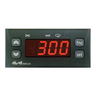
USER INTERFACE
The user has a display and four keys for
controlling status and programming of the
instrument.
DISPLAY
out
IC912LX
Scrolls through the menu items UP button
Increases the values
Parameter programmable
(par. H31)
Scrolls through the menu items
Decreases the values
Parameter programmable
(par. H32)
KEYS AND MENUS
At start-up the instrument performs a
Lamp Test; for five (5) seconds the display
and the leds blink, in order to verify their
integrity and correct operation; afterwards
it will appear the label "Lod" (Loading) for
ten (10) seconds. The instrument has two
main menus: the "Machine Status" and
"Programming" menu.
press and release
(single press)
IC 912 LX Pt100°R
electronic controller with single output
and regulation in Réaumur degrees
Alarm
•ON for active alarm;
•blinking when a silenced alarm is
still present
f nc
set
out1
DOWN button
ACCESSING AND USING MENUS
The resources are arranged in a menu that
can be accessed by pressing and quickly
releasing the "set" button (Machine Status
menu) or holding down the "set" button
for more than 5 seconds (Programming
menu).
To access the contents of each folder indi-
cated by the relevant label, just press the
"set" button once.
You can now scroll through the contents
of each folder, modify it or use its func-
tions. If you do not use the keyboard for
over 15 seconds (time-out) or if you press
the "fnc" button once, the last value
shown on the display is confirmed and
you are taken back to the previous screen
MACHINE STATUS MENU DIAGRAM
set
AL
SP1
LED
out1
Relay 1 (OUT1)
• ON for relay on (energized);
•blinking for protection delay or
enabling blocked
Soft Start / Setpoint
• ON when Set point is being set
fnc button
fnc
Set point button
set
MACHINE STATUS MENU
(See Machine Status Menu Diagram)
To access the Machine Status menu, press
the "set" button and quickly release it.
The "SP1" label appears.
(If alarms are active, with the exception of
faulty probes/probe errors, the "AL" label
appears).
By using the "UP" and "DOWN" buttons
you can scroll through the other folders in
the menu: the folders are indicated below
in the order they appear:
-SP1: Set point 1 setting folder or
-AL: alarm folder (if alarms present, with
exception of faulty probes/probe errors);
-Pb1: probe 1 value folder;
set
alarms
show alarms
set
SP1 value
change
SP1 value
t
• blinking when
Soft Start function is on
Set-point/ Reduced set point
•ON to modify Set-Point;
•blinking when reduced set point
is entered
ESC function (quit)
Parameter programmable
(par. H33)
1-Accesses Machine Status Menu
(SET POINTS, ACTIVE ALARMS,
PROBE READING) and labels/values;
1-Accesses Programming Menu
(PARAMETERS, COPY C ARD) and
relative labels/values;
3-Confirms commands
4-Activates the functions*
if alarm(s)
present
Advertisement
Table of Contents

Related Manuals for Eliwell IC 912 LX Pt100 R


Summary of Contents for Eliwell IC 912 LX Pt100 R
- Page 1 IC 912 LX Pt100°R cod. 9IS23094 electronic controller with single output rel. 11/04 and regulation in Réaumur degrees USER INTERFACE The user has a display and four keys for out1 controlling status and programming of the instrument. Alarm Relay 1 (OUT1) •...
- Page 2 HOW TO SET THE SET POINT Go to the “Machine Status” menu, press the “set” button and quickly release it. The “SP1” folder label appears. The Set point value appears on the display. To change the Set point 1 (2) value, press the “UP” and “DOWN” buttons within 15 seconds. If parameter LOC = y the Set points cannot be changed.
- Page 3 PROGRAMMING MENU the programming menu will appear. *PASSWORD (See Programming Menu Diagram) Passwords “PA1” and “PA2” allow level 1 1) Displaying level 1 parameters The level 2 parameters can be protected and level 2 parameters to be accessed. To access the Programming menu, hold by a second PASSWORD* (defined by There are no passwords in the standard the “set”...
- Page 4 Serial: TTL for connection to Copy Card RESPONSIBILITY AND RESIDUAL RISKS INSTALLATION and TelevisSystem. Eliwell & Controlli s.r.l. shall not be liable for any dam- ages deriving from: Analogue input: one PT100 input. The instrument is designed for panel - installation/use other than that prescribed and, in par- Digital inputs: 1 voltage-free digital input.
- Page 5 **NOTE: At level 1 the folders will show only level 1 parameters. At level 2 the folders will show only level Tab. 1 Parameter Table 2 parameters. PAR. DESCRIPTION RANGE DEFAULT* VALUE** LEVEL** U.M. REGULATOR 1 (folder with “rE1” label) Heat/Cool Mode.
- Page 6 DESCRIPTION RANGE DEFAULT* VALUE** LEVEL** PAR. U.M. CONFIGURATION (folder with “CnF” label) Time to enable keys, if these are configured for a specific func- 0…15 tion. For ESC, UP and DOWN keys configured for specific function (defrost, aux, etc) it set the elapsed time for the manual activa- tion of the related function.
- Page 7 DIAGNOSTICS DIAGNOSTICS Alarm table Table of faulty probes The alarm condition is always signalled by the buzzer (if present) and by the led of ALARM DISPLAY FAULT DISPLAY the alarm icon AH1** High temperature alarm (referring to Faulty probe 1 (thermostat control) probe Pb1/Pb2 based on par.
- Page 8 Telephone +39 0437 986111 ments in an RS-485 network. The BusAdapter device needs the BlueCard activation Facsimile +39 0437 989066 module supplied with the Eliwell soft- Internet http://www.eliwell.it ware package licence to be plugged in. RS485 Technical Customer Support: Email: techsuppeliwell@invensys.com...
Need help?
Do you have a question about the IC 912 LX Pt100 R and is the answer not in the manual?
Questions and answers