
Related Manuals for Atmel STK525


Summary of Contents for Atmel STK525
- Page 1 STK525 ..................... Hardware User Guide...
-
Page 2: Table Of Contents
2.10 Test Points ....................2-23 2.11 Configuration Pads .................2-24 2.12 Solder Pads ....................2-25 Section 3 Troubleshooting Guide ............... 3-26 Section 4 Technical Specifications ..............4-27 Section 5 Technical Support ................5-28 Section 6 Complete Schematics ................. 6-29 STK525 Hardware User Guide User Guide 7608A–AVR–04/06... -
Page 3: Introduction
To complement the evaluation and enable additional development capability, the STK525 can be plugged into the Atmel STK500 Starter Kit Board in order to use the AT90USBxxx with advanced features such as variable VCC, variable VRef, variable XTAL, etc. and supports all AVR development tools. -
Page 4: Stk525 Starter Kit Features
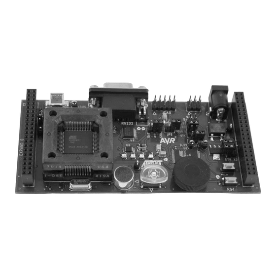
Introduction Figure 1-1 . STK525 Board STK525 Starter Kit Features The STK525 provides the following features: AT90USBxxx TQFP device (2.7V<Vcc<5.5V), AVR Studio® software interface USB software interface for Device Firmware Upgrade (DFU bootloader) STK500 compatible Power supply flagged by “VCC-ON” LED: –... - Page 5 Numerous access points for test. Notes: 1. The STK525 is supported by AVR Studio®, version 4.12SP2 or higher. For up-to-date information on this and other AVR tool products, please consult our web site. The newest version of AVR Studio®, AVR tools and this User Guide can be found in the AVR section of the Atmel web site, http://www.atmel.com.
-
Page 6: Using The Stk525
Section 2 Using the STK525 This chapter describes the board and all its features. Overview Figure 2-1 . STK525 Overview USB MiniAB RS232 JTAG External Power C Sensor Vcc Src. Vbus Gen. Pin1 Setting Setting Data Flash LEDS TQFP64 Socket... -
Page 7: Power Supply
USB connector, JACK PWR connector (J6, See Figure 2-2), STK500 USB powered: When used as a USB device bus powered application, the STK525 can be powered via the USB VBUS power supply line. JACK PWR connector: – Need of a male JACK outlet, –... - Page 8 This should be used for a typical USB Reg 5 device “bus powered” application. VBUS VBUS 5 Reg 3.3 In this mode, the STK525 is powered (4,7V to 5.0V) directly from the USB bus, and no VBUS 5 other external power supply is required.
- Page 9 5V power supply over the VBUS pin of its USB mini AB connector. A couple of transistors on the STK525 allows the UVCON pin of the AT90USBxxx to control the VBUS generation (See Figure 2-4). In this mode the STK525 is powered by external power supply source (J6 or STK500 expand0/1 connectors).
-
Page 10: Reset
Using the STK525 2.2.4 “POWER-ON“ LED The POWER-ON LED is always lit when power is applied to STK525 regardless of power supply source and the regulation. Figure 2-5 . “VCC-ON” LED RESET Although the AT90USBxxx has its on-chip RESET circuitry (c.f. AT90USBxxx Datasheet, section “System Control and Reset), the STK525 provides the AT90USBxxx... -
Page 11: At90Usbxxx Avr Microcontroller
“STK500 Resources” on page 19 Serial Links 2.5.1 The STK525 is supplied with a standard USB mini A-B receptacle. The mini AB receptacle allows to connect both a mini A plug or a mini B plug connectors. Figure 2-7 . USB mini A-B Receptacle When connected to a mini B plug, the AT90USBxxx operates as an “USB device”... - Page 12 The AT90USBxxx is a microcontroller with an on-chip USART peripheral (USART1). Only the asynchronous mode is supported by the STK525. The STK525 is supplied with a RS-232 driver/receiver. One female DB9 connector assumes the RS-232 connections. Figure 2-8 . RS-232 DB9 Connector Figure 2-9 .
- Page 13 Using the STK525 The STK525 USART implementation allows an optional hardware flow control that can be enabled thanks to SP4, SP5, SP7, SP8 solder pads (See Figure 2-11). Figure 2-11 . USART Schematic RS232 Interface 100nF 100nF 100nF PD[7..0] RS 232...
-
Page 14: On-Board Resources
2.6.2 LEDs The STK525 includes 4 green LEDs implemented on one line. They are connected to the high nibble of “Port D” of AT90USBxxx (PORTD[4..7]). To light On a LED, the corresponding port pin must drive to high level. To light Off a LED, the corresponding port pin must drive a low level. - Page 15 Figure 2-14 . LEDs Implementation Schematic In-line Grouped LEDs PD[7..0] LED 0 (green) TOPLED LP M676 LED 1 (green) TOPLED LP M676 LED 2 (green) TOPLED LP M676 LED 3 (green) TOPLED LP M676 STK525 Hardware User Guide 2-15 7608A–AVR–04/06...
- Page 16 10% at 25°C = Voltage value on ADC-0 input (V) ADC0 VCC = Board power supply The NTC thermistor used in STK525 has a resistance of 100 KΩ 5% at 25°C (T ) and a ± beta-value of 4250 ±3%. By the use of the following equation, the temperature (T) can be calculated: β...
- Page 17 Figure 2-15 . Thermistor Schematic 100k Temperature Sensor 2.6.4 Microphone The STK525 provides an electret microphone associated with its required preamplifier (See Figure 2-16), the interface is connected to ADC channel 2 of the AT90USBxxx microcontroller. STK525 Hardware User Guide 2-17 7608A–AVR–04/06...
- Page 18 MICROPHONE 2.6.5 Data Flash Memory For mass-storage class demonstration purposes, the STK525 provides an on-chip serial Flash memory (AT45DB321x) connected to the AT90USBxxx Serial Port Interface (SPI). The data-flash chip select signal is connected to PortB bit 4 of the AT90USBxxx (See Figure 2-17).
-
Page 19: Stk500 Resources
Using the STK525 STK500 Resources Figure 2-18 . Connecting STK525 to the STK500 Board Note: Caution: Do not mount an AVR microcontroller on the STK500 board when STK525 is plugged on STK500. 2.7.1 Supply Voltage from STK500 The AVR supply voltage coming from STK500 (VTG) can also be controlled from AVR Studio®. -
Page 20: In-System Programming
AT90USBxxx. This is the easiest and fastest way to reprogram the device directly over the USB interface. The “Flip” PC side application available for free on Atmel website offers a flexible and user friendly interface to reprogram the application over the USB bus. - Page 21 The AVR ISP programming interface is integrated in AVR Studio®. To program the device using AVR ISP programmer, connect the 6-wire cable on the ISP connector of the STK525 as shown in Figure 2-20. Note: See AVR Studio® on-line Help for information.
- Page 22 Using the STK525 To program the device using ISP from STK500, connect the 6-wire cable between the ISP6PIN connector of the STK500 board and the ISP connector of the STK525 as shown in Figure 2-18. Note: See AVR Studio® on-line Help for information.
-
Page 23: Test Points
Debugging 2.9.1 Debugging with AVR JTAG ICE mkII Every STK525 can be used for debugging with JTAG ICE MK II. Connect the JTAG ICE mkII as shown in Figure 2-21, for debugging help, please refer to AVR Studio® Help information. -
Page 24: Configuration Pads
This configuration pad is used to disconnect/connect the pot. (PF1) potentiometer from STK525. This configuration pad is used to disconnect/connect the Mic.(PF2) microphone preamplifier output from STK525. 2.11.2 Configuration Pads - Disconnection Figure 1. Configuration Pad - Disconnection Cut Connection 2.11.3... -
Page 25: Solder Pads
This solder pad allows to enable the physical CTS signal for RS-CTS hardware control flow on RS232 interface. This solder pad allows to enable the physical RTS signal for RS-RTS hardware control flow on RS232 interface. STK525 Hardware User Guide 2-25 7608A–AVR–04/06... -
Page 26: Troubleshooting Guide
STK525 ISP header (page 21) Connect the AVR ISP 6-PIN header to The AVR ISP probe is the correct STK525 ISP header (page not connected The AVR JTAG ICE Connect the JTAG ICE 10-PIN header to The AT90USBxxx cannot... - Page 27 Troubleshooting Guide STK525 Hardware User Guide 3-27 7608A–AVR–04/06...
-
Page 28: Technical Specifications
– External Voltage Supply ............9V -15V (100mA) Connections – USB Connector ..............Mini AB receptacle – USB Communications ............Full speed/low speed – RS 232C Connector .............9-pin D-SUB female – RS 232C Communications Maximum Speed ........250 kbps STK525 Hardware User Guide 4-28 7608A–AVR–04/06... -
Page 29: Technical Support
Section 5 Technical Support For Technical support, please contact avr@atmel.com. When requesting technical support, please include the following information: Which target AVR device is used (complete part number) Target voltage and speed Clock source and fuse setting of the AVR... -
Page 30: Complete Schematics
Section 6 Complete Schematics On the next pages, the following documents of STK525 revision 4381A are shown: Complete schematics, Assembly drawing, Bill of materials. Default configuration summary STK525 Hardware User Guide 6-30 7608A–AVR–04/06... - Page 31 Complete Schematics Figure 6-1 . Schematics, 1 of 5 STK525 Hardware User Guide 6-31 7608A–AVR–04/06...
- Page 32 Complete Schematics Figure 6-2 . Schematics, 2 of 5 6-32 STK525 Hardware User Guide 7608A–AVR–04/06...
- Page 33 Complete Schematics Figure 6-3 . Schematics, 3 of 5 STK525 Hardware User Guide 6-33 7608A–AVR–04/06...
- Page 34 Complete Schematics Figure 6-4 . Schematics, 4 of 5 6-34 STK525 Hardware User Guide 7608A–AVR–04/06...
- Page 35 Complete Schematics Figure 6-5 . Assembly Drawing, 1 of 2 (component side) Figure 6-6 . Assembly Drawing, 2 of 2 (solder side) STK525 Hardware User Guide 6-35 7608A–AVR–04/06...
- Page 36 FDV304P/FAI MOSFET P SOT23 SUB-D9 FEMALE 90° with harpoons Q1,Q2 BC847B SOT23 IC peak=200mA R1,R2 1/16W-5% SMD CASE 0602 R3,R5 1/16W-5% SMD CASE 0603 R4,R6,R7,R17,R27 CASE 0603 CASE 0604 R9,R25,R29,R32 1/16W-5% SMD CASE 0603 6-36 STK525 Hardware User Guide 7608A–AVR–04/06...
- Page 37 STK500 Analog Ref VTG33 Short 3.3V to VTG (Mass storage extension board) UCAP Short UCAP with Uvcc Vcc Src Vcc Selection 3.4 shorted Vbus Gen VBUS generation selection (host mode) 2.3 shorted Solder PADS STK525 Hardware User Guide 6-37 7608A–AVR–04/06...
- Page 38 Bypass limiter OPEN RS232 hardware control enable OPEN RS232 hardware control enable OPEN Configuration PADS Bypass CTN in on PF0 CLOSE Bypass Potentiometer ADC in on PF1 CLOSE Bypass Mic In on PF2 CLOSE 6-38 STK525 Hardware User Guide 7608A–AVR–04/06...
- Page 39 Disclaimer: The information in this document is provided in connection with Atmel products. No license, express or implied, by estoppel or otherwise,to anyintellectu- alproperty right is granted by this document or in connection with the sale of Atmel products. EXCEPT AS SET FORTH IN ATMEL’S TERMS AND CONDI-TIONS OF SALE LOCATED ON ATMEL’S WEB SITE, ATMEL ASSUMES NO LIABILITY WHATSOEVER AND DISCLAIMS ANY EXPRESS, IMPLIED OR STATUTORYWAR-...
- Page 40 Mouser Electronics Authorized Distributor Click to View Pricing, Inventory, Delivery & Lifecycle Information: Microchip ATSTK525...
Need help?
Do you have a question about the STK525 and is the answer not in the manual?
Questions and answers