
Related Manuals for SAJ Sununo-TL Series


Summary of Contents for SAJ Sununo-TL Series
- Page 1 Installation Manual SAJ Solar Inverter Sununo-TL Series Sununo-TL1.5K\Sununo-TL2K\Sununo-TL3KB\Sununo-TL4KB Sununo-TL3KA\Sununo-TL4KA\ Sununo-TL5K Please read this manual carefully before installation.
-
Page 2: Table Of Contents
DC side Connection .................... 13 Pre-running Inspection ....................16 DC Side Inspection ..................... 16 AC Side Inspection ..................... 17 Communication Inspection ................. 17 Operation method ......................17 Start SAJ Solar Inverter ..................17 Key Operation ....................17 Contact SAJ ........................19... -
Page 3: Introduction
1 Introduction This manual introduces the installation and configuration of below models of SAJ Solar Inverters. Sununo-TL1 .5K\Sununo-TL2K\Sununo-TL3KB\Sununo-TL4KB Sununo-TL3KA\Sununo-TL4KA\ Sununo-TL5K Only qualified electricians who have read and fully understood all safety regulation contained in this manual can install the inverter. Installers must be aware of native regulations, laws and safety requirements. -
Page 4: Assembly Parts
Assembly Parts After you receive the SAJ Solar Inverter, please check if there is any damage on the carton. Please also check the inside completeness and for any visible external damage on the inverter or any accessories. Contact your dealer if anything is damaged or missing. - Page 5 Object Quantity Description SAJ Solar Inverter Rear Panel DC Connector (for Sununo-TL1.5K/2K ) 1 Sets DC Connector (for 2Sets Sununo-TL3KB/4KB/3KA/4KA/5K) RS485Connector M6×50 Expansion screw Expansion tube M4×12 Cylinder head screw and Lock washer ( Sununo-TL1.5K/2K/3KB/4KB ) M5×12 Cylinder head screw and Lock washer (...
-
Page 6: Installation
3 Installation 3.1 Installation Mode Noted: Ensure the label visible on the SAJ Solar Inverter after installation. Please see more details installation information in the User Manual. Avoid prolonged rain. Avoid direct sunlight. Avoid direct sunlight. Ensure sufficient airflow. -
Page 7: Safety Clearance
Install on the wall correctly. Figure 3.1 3.2 Safety Clearance Please follow up the safety clearance below when install one or multiple SAJ Solar Inverter. Please contact SAJ for more installation information. Direction Minimum Clearance(cm) Above Below Side Front Figure 3.2 3.3 Mounting Procedure. - Page 8 Sununo-TL1.5K/2K Sununo-TL3KB/4KB Sununo-TL3KA/4KA Sununo-TL5K Figure 3.3 2) Drill 6 holes in the wall (in conformity with position marked in above picture), and then place expansion tubes in the holes using a rubber hammer. Figure 3.4 3) Mount the rear panel. Wring six screws into the expansion tubes and tightly mount the rear panel on the wall.
- Page 9 Figure 3.5 4) Carefully attach the inverter to the rear panel according to the position of the screws. Make sure the backside of the inverter is closely against the rear panel. When two people transport the inverter, make sure each one use the hand grip in right position as illustrated in the picture.
-
Page 10: Special Installation (Only For France)
3.4 Special Installation (only for France) Connect the ground wire to the earthing, terminal, and then tighten them as following figure. Figure 3.8... -
Page 11: Electrical Connection
4 Electrical Connection 4.1 Overview of connection area Sununo-TL1.5K/2K Sununo-TL3KB/4KB... -
Page 12: Ac Side Connection
Sununo-TL3KA/4KA/5K Figure 4.1 Object Description DC switch to turn off the inverter manually(optional) DC input Plug for connecting the RS485 communication module Plug for connecting Ethernet communication module(optional) AC output Heat sink 4.2 AC Side Connection NOTICE The cross-section of the AC cable should be more than 12 AWG. DANGER ... - Page 13 Assembly Instructions: 1) Strip the cable with the length 0.276 inches (9/32″) - (7mm) and please be careful NOT to nick conductors. Figure 4.2 2) Screw off and separate each component of AC connector as follows. Figure 4.3 3) Pass the cable through each component from right to the left as follows. Tighten the screws with 3N·m torque.
- Page 14 Figure 4.5 Connect L, N and protective conductor to the AC terminal in accordance with the label. To do this, the insulated earthling conductor must be 5mm longer than the insulated L and N conductors! L and N must not be swapped. The ground wire shall be larger than phase conductor.
-
Page 15: Dc Side Connection
Finally, connect the straight plug to the AC terminal on inverter. Pay attention to the polarity of the terminals to avoid wrong connecting. 4.3 DC side Connection NOTE The cable length on DC side should not exceed 30 m. DANGER ... - Page 16 Male side connector (M) Female side connector (F) Figure 4.8 Assembly Instructions: 1) Strip the cable with the length 0.276 inches (9/32")-(7mm) and please be careful NOT to nick conductors. Figure 4.9 2) Use specified strip tool in this step. Adjust the strip stopper and put the cable in corresponding notch to strip the length of 7mm.
-
Page 17: Cable Requirements
Pin contact Socket contact Figure 4.12 Figure 4.13 4) Crimp contact barrel by using the hex crimping die, ensure it is fixed.See below figures. Crimped pin contact Crimped socket contact Figure 4.14 Cable requirements: Cable Size Cable pull – out force requirement 2.5 mm Min. -
Page 18: Pre-Running Inspection
Max. DC Voltage and Min. DC Voltage in the datasheet).DC voltage exceeding the range may cause error or damage to the inverter and the lose caused is not covered by SAJ warranty policy. The polarity of DC input should be in accordance with inverter input, and not the reverse. -
Page 19: Ac Side Inspection
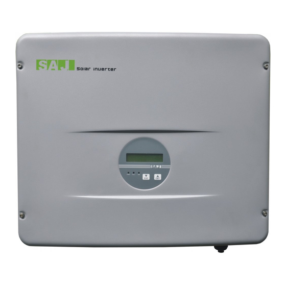
5.2 AC Side Inspection Ground cable should be in appropriate cross section size. An over-long or over-slender ground cable can lead to inverter errors. SAJ should not bear responsibility to any defect or safety accident caused by an absence of ground cable. - Page 20 Figure 6.2 Object Description LED light – POWER. Yellow light shines when the inverter is energized. LED light-FAULT. Red light shines when fault occurs in the inverter and automatically goes out when the fault is removed. LED light-RUN. Green light flashes when the inverter runs good. ▼/ESC ▲/ENT LCD screen for viewing the running data, recorded information, and...
-
Page 21: Contact Saj
7 Contact SAJ Guangzhou Sanjing Electric Co., Ltd. Add:No.17, Xiangshan Road Guangzhou Science City, Guangdong, China P.R.C. Zip: 510663 http://www.saj-solar.com Technical Support & Service: Tel:+86 20 6660 8619 Fax:+86 20 6660 8589 E-mail:service@sajelec.com International Sales: Tel:+86 20 6660 8618/6660 8532 Fax:+86 20 6660 8589 E-mail:info@sajelec.com...
Need help?
Do you have a question about the Sununo-TL Series and is the answer not in the manual?
Questions and answers