Table of Contents

Related Manuals for Erone ERONE 433 Series


Summary of Contents for Erone ERONE 433 Series
- Page 1 S E L 2 6 4 1 R 4 3 3 C 4 S E L 2 6 4 1 R 4 3 3 V 4 Thank you for choosing a product Erone. You are recommended to read carefully this manual before installing the product.
-
Page 2: Memory Management
SUMMARY 1- PRODUCT OVERVIEW 2- INTRODUCTION 3- TECHNICAL SPECIFICATIONS 4- MAIN FEATURES 5- INSTALLATION Positioning Fixing Connections 6- RECEIVER LAYOUT 7- TRANSMITTER CODE MEMORISATION Transmitter memorising using the receiver buttons P1, P2, P3, P4 Transmitter memorising without access to the receiver using the keys of the transmitter 8- RELAYS OPERATING MODE SETTING Relay operating mode display... -
Page 3: Product Overview
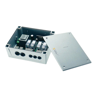
1- PRODUCT OVERVIEW Cover 4 screws for the cover fixing 4 screws for The box fixing 4 plugs Antenna Receiver box T H E S M A R T L I V I N G... - Page 4 Erone 433 - SEL 2641 R433 V4: 4 Channels receiver with 230 Vac power supply Erone 433 - SEL 2641 F433 C4: 4 Channels receiver FM with 12 / 24 Vac/dc power supply Erone 433 - SEL 2641 F433 V4: 4 Channels receiver FM with 230 Vac power supply Usable transmitters Erone 024A Mod.
-
Page 5: Technical Specifications
3 - TECHNICAL SPECIFICATIONS Types Characteristics SEL 2641R433V4 SEL 2641R433C4 SEL 2641F433V4 SEL2641F433C4 Receiver type: Superheterodyne Superheterodyne Carrier frequency: 433.92 MHz 433.92MHz Local oscillator frequency: 433.42 MHz 433.42MHz Demodulation: AM/ASK AM/ASK Input load: 50 Ohm 50 Ohm Channel width: > 25 KHz >... -
Page 6: Main Features
4 - MAIN FEATURES # Selflearning and cancelling of the transmitter codes without accessing to the receiver; # 255 transmitter keys storable; # Stored transmitter number display; # Display of the last received transmitter code; # Replacement of a stored code; # Total memory erasure;... - Page 7 Connections 2 -Fuse (fig. 5) The fuse F1 of 315 mA it is used for the electronic card protection. 1 - Power supply (fig.4) ATTENTION: The connections differ upon the type. Mod. SEL 2641 R433 V4 Fig 5 Connect the Mains 230 Vac to the following terminals (fig.
-
Page 8: Receiver Layout
6 - RECEIVER LAYOUT DL1(Red Led ): Displays the Pulse mode (of the selected relay ); DL2(Green Led ): Displays the Step mode (of the selected relay ); Dl3(Red Led ): Displays the Timered mode (of the selected relay ); DL4(Red Led ): Displays the operating mode in Reduced range (of the selected relay );... - Page 9 7B) : Memorisation of transmitters without accessing to the receiver The memorization effects using only the transmitter keys There are 2 cases: 1) the receiver is virgin and you need to memorise the first transmitter; 2) in the receiver it is already present in memory a transmitter and you have to memorise the following transmitters.
- Page 10 8 - RELAYS OPERATING MODE SETTING The relays can be programmed in 3 different modes: Impulsive (pre-planned), Bistabile (or step), Delayed. For each of these possibilities it is possible besides to plan the range reduction function that decreases the sensitivity of the receiver, preventing the receipt from great distance. The configuration of each relay is displayed by the lighting of the corresponding led: - DL1 points out that the relay is planned in impulsive mode;...
- Page 11 8E ) Relay release time programming The release time after which the relay programmed as delayed releases is programmable. The value of the time can be introduced making use of the buttons P1 and P2. Through 8 pressures on P1 and P2, to which correspond as many lightings of the leds DL1(Red) and DL2 (Green), it is possible to introduce a number in binary coding that gives the value of the delay.
- Page 12 ( during the acustic signal ) press the key of the new transmitter. GUARANTEE The guarantee period of all Erone products is 24 months, beginning from the manufacturer date. During this period, if the product does not work correctly, due to a defective component, the product will be repaired or substituted at the discretion of the producer.
Need help?
Do you have a question about the ERONE 433 Series and is the answer not in the manual?
Questions and answers