Advertisement
Installation guide
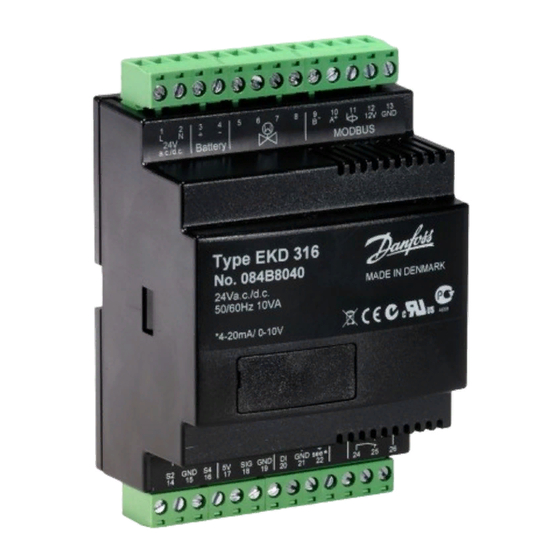
Electronic superheat controller - Modbus version
Type EKD 316C (Colibri®)
Introduction
EKD 316 is a superheat controller that can be used where there are requirements for accurate control of superheat.
Typically it will operate in Commercial air conditioning, heat pumps, commercial refrigeration, food retail and
industrial application. Compatible valve - Danfoss ETS / ETS C, KVS / KVS C and CCM / CCMT valves.
24 V AC / DC ±15%, 50/60 Hz, 22 VA / 15 Watt
Supply voltage
(the supply voltage is not galvanically
separated from the input and output signals)
Controller
Power consumption
ETS C / KVS C
ETS, KVS, CCM, CCMT
Current signal *
Voltage signal *
Input signal
*)Ri: mA: 400 Ohm
Pressure transmitter
e.g. AKS 32R
V: 50 kOhm
Digital input from external contact function
Sensor input
2 pcs. Pt 1000 ohm
Alarm relay
1 pcs. SPDT
Step motor output
Pulsating 30 - 300 mA
Data communication RS 485 Modbus data communication
Operations
Transportation
Environments
Humidity 20 - 80 % Rh, none condensing
No shock influence/vibrations
Enclosure
IP 20
Compatible valves
Bipolar stepper motor valves
Standalone controller
Valve driver
DKRCC.PI.RR0.A3.02
5 VA
7.2 VA
1.3 VA
4 - 20 mA or 0 - 20 mA
0 - 10 V or 1 - 5 V
0.5 - 4.5V DC ratiometric type
(10% - 90% of supply voltage)
DI : < 800 Ohm = ON
DI : > 30 kOhm = OFF
Max 24V, 1A resistive - Class II
0 – 55 °C / 32 – 131 °F
-40 – 70 °C / -40 – 158 °F
ETS Colib ri®
ETS Colib ri®
ENGINEERING
T O M O R R O W
Danfoss
Danfoss
R64-3002.1
R64-3002.11
OD
I/V
I/V
© Danfoss A/S (AC-MCI / sw), 2016-12
English
Advertisement
Table of Contents

Subscribe to Our Youtube Channel
Summary of Contents for Danfoss EKD 316C Colibri
- Page 1 Typically it will operate in Commercial air conditioning, heat pumps, commercial refrigeration, food retail and industrial application. Compatible valve - Danfoss ETS / ETS C, KVS / KVS C and CCM / CCMT valves. 24 V AC / DC ±15%, 50/60 Hz, 22 VA / 15 Watt...
- Page 2 • By connecting any EKD 316C inputs to mains voltage will permanently damage the controller. • Do not apply voltage to the controller before the wiring is completed. Connection of the terminals to earth will destroy the controller. 21,22 DKRCC.PI.RR0.A3.02 © Danfoss A/S (AC-MCI / sw), 2016-12...
- Page 3 Note: If a switch is not connected, terminals 20 and 21 must be short circuited. Do not connect external power supply to these terminals, else it will damage the controller. 24 - 26 Alarm relay: There is connection between 24 and 26 in alarm situations. DKRCC.PI.RR0.A3.02 © Danfoss A/S (AC-MCI / sw), 2016-12...
- Page 4 24 V AC / DC Modbus Modbus – – EKA 164A Fuse 2 A Fuse 2 A PLC controller PLC cont Fuse 2 A Alarm relay Alarm relay Alarm relay – switch Analog signal PLC controller DKRCC.PI.RR0.A3.02 © Danfoss A/S (AC-MCI / sw), 2016-12...
-
Page 5: Important Note
• SPDT relay, connected to terminals 24 - 26 can be used either to connect solenoid valve or to connect alarm. • Relay is designed for switching max. 24 V, 1A resistive - Class II. DKRCC.PI.RR0.A3.02 © Danfoss A/S (AC-MCI / sw), 2016-12... - Page 6 The default unit address is 240 which, can be changed using parameter “03 unit address”. Modbus Not in use Danfoss 84N404.10 Detail explanation on Modbus installation and software parameter setting can be found on Installation guide RC8AC602 and manual DKRCC.PS.RI0.F1.02. DKRCC.PI.RR0.A3.02 © Danfoss A/S (AC-MCI / sw), 2016-12...
- Page 7 • The stepper motor is connected to terminals 5 to 8 (see terminal assignment) with M12 motor cable. • To configure stepper motor valves other than Danfoss stepper motor valve, it is necessary to set the right valve parameters as described on section Valve configuration. The default valve setting in EKD 316C is 16 (i.e.
-
Page 8: Parameter Name
Compensation for spindle play Motor current (mA) 3051 Define the require current in mA RMS. Note: Please refer to Danfoss EKD 316 manual for details. Parameter setup Setting controller in valve driver mode Setting controller in Superheat control mode. using analog signal... - Page 9 -2255 Rfg.Fac.A3 2550 1000 3000 2557 2557 Sensors Temp.unit Adjust S2 [K] Adjust S4 [K] Min. Trans. Pres. 2034 (bar relative) Max. Trans. Pres. 2033 (bar relative) Enable high pressure alarm 2199 DKRCC.PI.RR0.A3.02 © Danfoss A/S (AC-MCI / sw), 2016-12...
-
Page 10: Installation Considerations
Electronic controls are no substitute for normal, good engineering practice. Danfoss will not be responsible for any goods, or plant components, damaged as a result of the above defects. It is the installers responsibility to check the installation thoroughly, and to fit the necessary safety devices.


Need help?
Do you have a question about the EKD 316C Colibri and is the answer not in the manual?
Questions and answers