
Subscribe to Our Youtube Channel
Related Manuals for Amprobe SOLAR-500


Summary of Contents for Amprobe SOLAR-500
- Page 1 SOLAR-500 Solar Analyzer Users Manual • Mode d’emploi • Bedienungshandbuch • Manual d’Uso • Manual de uso...
- Page 2 SOLAR-500 Solar Analyzer Users Manual July 2009, Rev.1 ©2009 Amprobe Test Tools. All rights reserved. Printed in Taiwan...
- Page 3 Limited Warranty and Limitation of Liability Your Amprobe product will be free from defects in material and workmanship for 1 year from the date of purchase. This warranty does not cover fuses, disposable batteries or damage from accident, neglect, misuse, alteration, contamination, or abnormal conditions of operation or handling. Resellers are not authorized to extend any other warranty on Amprobe’s behalf.
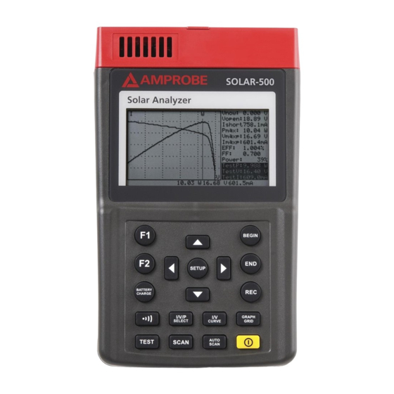
- Page 4 SOLAR-500 Solar Analyzer A) Front Panel...
-
Page 5: Power Button
SOLAR-500 Solar Analyzer Button F1Button: (Reserved) In the SETUP menu, press button to select previous item F2 Button: (Reserved) Button Battery Charge Button In the SETUP menu, press button to select next item When Solar Module Analyzer is turned on, press BATTERY CHARGE button to... - Page 6 SOLAR-500 Solar Analyzer B) Rear Panel 1) Communication Window To connect Solar Analyzer with PC via USB cable 2) Stand 3) Battery Cover 4) Screw of Battery Cover C) TOP Panel (Connectors) 1) T+ Terminal (Kelvin Clips) 5) I+ Terminal (Alligator Clips)
-
Page 7: Table Of Contents
SOLAR-500 Solar Analyzer CONTENTS SYMBOLS, WARNINGS AND PREPARATION ............2 UNPACKING AND INSPECTION ................2 INTRODUCTION ....................3 OPERATION ......................7 Preparation ....................... 7 Precaution ......................8 Connecting Diagram ..................9 Selected Condition of Auto Scan, Manual Scan, or Test Auto Scan ....10 Auto Scan ...................... -
Page 8: Symbols, Warnings And Preparation
Do not operate this instrument in the presence of gasoline, natural gas, propane, or in other combustible atmospheres. UNPACKING AND INSPECTION Your shipping carton should include: SOLAR-500 Solar Analyzer Carrying Bag Users Manual AC Adaptor RS232C (to USB Bridge) Cable... -
Page 9: Introduction
INTRODUCTION The SOLAR-500 can be used in Quality Control for Production Line, Warehouse or Site of Installation. Manufacturers of solar panels can test the characteristics for quality control purpose in the production line. Due to the advantage of portability of the unit, quality inspectors can randomly pick samples of solar panels and test them in the warehouse to assure quality before shipment. - Page 10 Example B: Maintenance of Solar Panels Abnormal I-V Curve (Cells at the corner of solar panel are defected)
- Page 11 Abnormal I-V Curve (defected cells scattered over the solar panel) The technicians or maintenance engineers can store the characteristics data of solar panels in the beginning. And compare the characteristics data in the weekly, monthly or yearly maintenance. If the characteristics of any solar panels are different from the previous data, technicians or maintenance engineers can further identify the problems of solar panels.
- Page 12 Feature • I-V Curve Test for Solar Cell. • Single Point I-V Test. • Maximum Solar Power (Pmax) search by auto-scan. • Maximum Voltage (Vmaxp) at Pmax. • Maximum Current (Imaxp) at Pmax. • Voltage at open circuit (Vopen). • Current at short circuit (Ishort). •...
-
Page 13: Operation
OPERATION Preparation This Solar Module Analyzer uses rechargeable batteries. Before using new rechargeable batteries, please charge them first for 10~12 hours continuously for better battery life. The charging steps are: 1. Unscrew and remove the battery cover. 2. Put in new recharging batteries (pay attention to the correct polarities). 3. -
Page 14: Precaution
Precaution WARNING! � when users see “Overheated” warning shown in LCD 1. Users must wait during this “Overheated: cooling” period before they start next simulation. 2. And if users would like to turn the unit off, they must wait for another 3 min. -
Page 15: Connecting Diagram
Connecting Diagram Kelvin Clip Connecting Diagram Alligator Clip Connecting Diagram... -
Page 16: Selected Condition Of Auto Scan, Manual Scan, Or Test Auto Scan
Selected Condition of Auto Scan, Manual Scan, or Test Users should first select AUTO SCAN ( ) to obtain a general idea of characteristics of a solar panel. 1. Press button to turn on the Analyzer. Properly connect the pair of Kelvin clips to the solar panel and the Analyzer. - Page 17 3. Press button to start MANUAL SCAN. After the scanning is finished, the result will come out like below. If users are interested in a specific point of test current, users can enter the current value for a Single Test Point. Press TEST ( ) to test the characteristics at the current.
-
Page 18: Auto Scan
Auto Scan 1. Press button to turn on the Analyzer. 2. Properly connect the pair of Kelvin clips to the solar panel and the Analyzer. The red Kelvin clip is for positive pole and the black Kelvin clip for negative pole. (refer to above Connecting Diagram). 3. -
Page 19: Manual Scan
Manual Scan 1. Press button to turn on the Analyzer. 2. Properly connect the pair of Kelvin clips to the solar panel and the Analyzer. The red Kelvin clip is for positive pole and the black Kelvin clip for negative pole. 3. -
Page 20: Single Point Test
Single Point Test 1. Press button to turn on the Analyzer. 2. Properly connect the pair of Kelvin clips to the solar panel and the Analyzer. The red Kelvin clip is for positive pole and the black Kelvin clip for negative pole. 3. -
Page 21: Save Testing Results
Save Testing Results When users finish a test (by taking one of the above-mentioned methods; Auto-scan, Manual-scan or Single Point Test), the testing result can be saved in the memory of the analyzer. The procedures of saving testing results: 1. Perform a test by Auto-scan, Manual-scan or Single point test. 2. -
Page 22: Clear Recorded Testing Data
Clear recorded testing data Users can clear the recorded testing data in the Analyzer. The procedures of deleting saved data: 1. Keep pressing (REC) button and turn on the Analyzer (i.e. press button ) at the same time. 2. After turning on the Analyzer, all the data recorded in the Analyzer (memory) will be deleted. -
Page 23: Setup Menu
Setup Menu 1. Press (SETUP) button to enter the Parameter Setting screen. 2. Press buttons to select the setting items. (1) Time delay before scan (2) Current Range of Scan begin (3) Current Range of Scan end (4) Area of Solar Cell or Panel (5) Irradiance (6) Single Test Point (7) Alarm of Low Power... -
Page 24: Specification
SPECIFICATION General Specifications Battery Type : Rechargeable, 2500mAh (1.2V) x 8 AC Adaptor : AC 110V or 220V input DC 12V / 1 ~ 3 A output Dimension : 257(L) x 155(W) x 57(H) mm (10.1 (L) x 6.1 (W) x 2.2 (H) in) Weight : 1160g / 40.0oz (Batteries included) Operation Environment : 0°C ~ 50°C (32°F ~ 122°F), 85% RH Temperature Coefficient : 0.1% of full scale / °C ( <18°C or >28°C ) -
Page 25: Electrical Specifications
Electrical Specifications (23°C ±5°C, Four-wire Measurement) DC Voltage Measurement Range (60V / 6A) Resolution Accuracy 0 ~ 6 V 0.001 V ± 1 % ± (1 % of Vopen ± 9 mV) 6 ~ 10 V 0.001 V ± 1 % ± (1 % of Vopen ± 0.09 V) 10 ~ 60 V 0.01 V ±... -
Page 26: Maintenance And Repair
MAINTENANCE AND REPAIR If there appears to be a malfunction during the operation of the meter, the following steps should be performed in order to isolate the cause of the problem. 1. Check the battery. Replace the battery immediately when LCD displays the Power is ≦2%. - Page 27 When regular batteries are used and LCD displays the Power is ≦2%, please replace the batteries: 1. Turn off the Solar Model Analyzer. 2. Remove the screw of the battery cover. 3. Lift and remove the battery cover. 4. Remove the old batteries and insert eight new 1.5V SUM-3 batteries. 5.
-
Page 28: Fuse Replacement
Fuse Replacement When the voltage can not be measured (Vnow = 0V) after properly connecting the Analyzer and the solar panel, please check the fuse. If the fuse is damaged (burned), please replace a new fuse by following the procedures: 1. - Page 29 Unscrew and remove the battery cover and the back cover. Location of Fuse...
-
Page 30: Pc Connection, Software Installation And Operation
PC Connection, Software Installation And Operation INTROODUCTION Operating Environment • Application program should be installed in the operation system of Microsoft Windows Vista/ XP / 2000 (SP3). • NI-VISA Runtime Engine should be installed (Application program will install it automatically). •... -
Page 31: Software Installation
SOFTWARE INSTALLATION Install Application Program Execute Install.bat (which is in installation disc) to enter the procedures of installing Application Program. Please follow the instructions to install Application Program. When performing the installation of Application Program, the USB driver program and NI-VISA Runtime Engine will be installed automatically. -
Page 32: Software Operation
SOFTWARE OPERATION Start Executing Program Step 1: n Start -> All Programs, choose “Solar Analyzer” or click the shortcut to start executing program. Step 2: Select the Serial Port connected to Solar Analyzer. Remark: 1. Click to select the Serial Port connected to Solar Analyzer. 2. -
Page 33: Parameter Setting
Parameter Setting Set up the parameters of Solar Analyzer. Remark: 1. Tool bar includes: Languages (Mandarin, English) and Exit. 2. Functions includes: Parameter Setting, Print LCD, Download, Scan. 3. Press the OK button on the right side of “Read ALL Parameter” to read all the present parameters of Solar Analyzer. -
Page 34: Save/Print Lcd
Save/Print LCD Save or print the present LCD data of Solar Analyzer. Remark: 1. Press “Read” button to read the present LCD data of Solar Analyzer.。 2. Press “Save as Bitmap” to save the present LCD data as a (single-color) bitmap. -
Page 35: Download
Download Download the logged data in the memory of Solar Analyzer. Remark: 1. Press “Download” to download the logged data in the memory of Solar Analyzer. 2. The red block in the center shows the Downloading status. 3. Press “Present Sample” to change the present sample (location) to last or next logged data. - Page 36 6. Export: to save/export the data (i.e. the Voltage/Current curve data) of Present Sample as/in a .CSV file for users to read in Excel. 7. I/V CURVE: to select the X-axis of the present curves based on I or V. 8.
-
Page 37: Auto Scan Solar Module
Auto Scan Solar Analyzer Auto Scan the Solar panel to obtain measurement results Remark: 1. Press “Auto Scan” to auto scan the solar pane. 2. The red block in the center shows the Auto Scan status. 3. Press “Present Sample” to change the present sample (location) to last or next logged data. - Page 38 6. Export: to save/export the data (i.e. the Voltage/Current curve data) of Present Sample as/in a .CSV file for users to read in Excel. 7. I/V CURVE: to select the X-axis of the present curves based on I or V. 8.
Need help?
Do you have a question about the SOLAR-500 and is the answer not in the manual?
Questions and answers