Table of Contents
Advertisement
Advertisement
Table of Contents

Related Manuals for JRC Radar 1000


Summarization of Contents
Symbols Used In This Manual
Warning and Caution Symbol Meanings
Explains the meaning of Warning and Caution symbols for user safety and equipment protection.
Prohibition and Instruction Symbol Meanings
Details the meaning of Prohibition and Instruction symbols for correct operational procedures.
Operating Precautions and Safety
Electrical Safety and Scanner Precautions
Covers safety measures related to electrical shock and the radar scanner unit during operation.
General Handling and Environmental Cautions
Advises on proper handling, installation environment, and avoiding damage to the equipment.
Equipment Overview
System Functionality
Details the primary function of the RADAR 1500 MK II as a navigation aid.
Key System Features
Highlights the main features and capabilities of the radar system for users.
System Components List
Lists all the components included with the RADAR 1500 MK II radar system.
Physical Dimensions of Units
Provides detailed mounting dimensions for the display and scanner units.
Component Identification and Functions
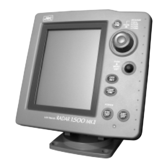
Control Panel Layout and Overview
Illustrates and names the main controls on the display unit's front panel.
Detailed Control Button Functions
Explains the operation of individual control panel keys, J-DIAL, and JOYSTICK.
Installation Guide
Unpacking and Installation Planning
Guidelines for unpacking, inspecting, and planning the optimal installation of the radar system.
Display Unit Mounting Procedures
Details considerations and methods for securely mounting the display unit.
Scanner Unit Mounting Guidelines
Provides instructions for selecting the location and mounting the radar scanner unit.
Scanner Unit Cable Connection
Instructions for connecting the interunit cable between the scanner and display units.
Electrical Connection and System Interface
Covers DC power connection and integrating with external NAV-AID and compass systems.
Initial Operation and Setup Procedures
Steps for post-installation inspection and accessing the initial setup menu.
Setup Menu Adjustments
Guides through essential adjustments like tuning, bearing, timing, and language settings.
Operation Guide
Control Layout and Screen Explanation
Identifies control panel elements and explains the radar display screen layout.
Radar Power On and Off Procedures
Instructions for turning the radar system on, transmitting, and entering standby mode.
Basic Operation Controls
Covers selecting range, adjusting receiver sensitivity (gain), and manual tuning.
Clutter Reduction and Display Settings
Guides on reducing sea/rain clutter and adjusting LCD contrast and panel illumination.
Range and Bearing Measurements
Methods for measuring target distance and bearing using VRM, EBL, and cursor.
Advanced Operation Features
Details menu navigation, guard zones, trails, data formats, and other advanced functions.
Maintenance Procedures
Preventive Maintenance Guidelines
Tips for routine checks and cleaning to ensure continuous, trouble-free operation.
Cleaning and Fuse Replacement
Instructions for monthly cleaning of units and replacing the system's fuse.
Technical Specifications
General System Specifications
Provides overall specifications including range, accuracy, and environmental conditions.
Scanner Unit Specifications
Details the technical specifications for the radar scanner unit, including dimensions and performance.
Display Unit Specifications
Lists the technical specifications for the display unit, including dimensions and video output.
Need help?
Do you have a question about the Radar 1000 and is the answer not in the manual?
Questions and answers