
Related Manuals for Yueming CMA0604-B-A

Summary of Contents for Yueming CMA0604-B-A
- Page 1 Product Operation Manual Applicable models: CMA0604-B-A/CMA1309-B-A/CMA1610-B-A/CMA1309-T-A/CMA1610-T-A Version:...
- Page 2 Copyright All rights reserved Our company reserves the right to modify the product and specifications on this manual without prior notice. Our company does not assume direct, indirect, special, incidental or consequential loss or liability due to improper use of this manual or the product. Our company is in possession of the patents, copyright and other intellectual property rights of the product and its software.
-
Page 3: Disclaimer And Responsibility Statement
Disclaimer and Responsibility Statement Whole suing the equipment from our company, users are required to ensure b integrity and independence of the product including but not limited to: mechanical, electrical, optical, control software and accessories. Unauthorized modification is strictly prohibited. It is a must to satisfy operating environment and operating specifications specified in the owner’s manual. -
Page 4: Foreword
Foreword Thank you for choosing our laser equipment! Before operating, please read this manual carefully to ensure proper use of our equipment. Please keep this manual properly for future reference. Due to different configurations, certain models do not have certain features listed in this manual. The actual product shall prevail. -
Page 5: Safety Precautions
Safety Precautions Before using the machine, users are required to carefully read this manual and other operating requirements, strictly abide by the operating specifications. Professional are required for operating the machine. Attention The machine uses class 4 laser (strong laser radiation). The laser radiation may possibly cause the following accidents: ... -
Page 6: Table Of Contents
Contents Copyright ..............................I Disclaimer and Responsibility Statement ....................II Foreword ..............................III Safety Precautions ..........................IV Chapter1 Equipment Introduction ......................3 Equipment Introduction ......................3 Product parameters ......................3 Operating environment ......................3 Equipment compositions ...................... 4 1.4.1 Compositions of the machine ....................4 1.4.2 Transmission system ...................... - Page 7 3.2.2 Emergency stop button (optional) ..................32 3.2.3 Monochromatic warning lamp (optional) ................33 3.2.4 Description of Operation Panel................... 34 Equipment debugging ......................34 3.3.1 Check before turning on ..................... 34 3.3.2 Movement debugging ......................35 3.3.3 Laser debugging ........................38 Chapter4 System Maintenance......................
-
Page 8: Chapter1 Equipment Introduction
1309: 1300 x 900 mm version: 0604: 600 x 400 mm B: Single-tip 1610: 1600 x 1000 mm T: Dual-tip A: Mechanical design version 1.2 Product parameters Model CMA0604-B-A CMA1309-B-A CMA1610-B-A Laser power(w) 80, 100, 130 Laser Laser wavelength (nm) 10640 Cooling method... -
Page 9: Equipment Compositions
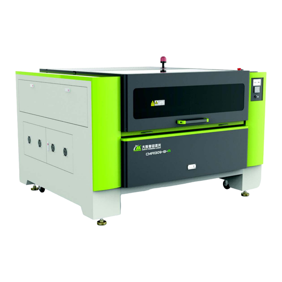
dry, and free of interference like dust, pollution, vibration, high power and strong Environment of the equipment magnetic field 1.4 Equipment compositions Due to different models and improvement of products, the industrial design and details of some types of machine may be different. The compositions are subject to the actual product. The following takes general CMA1309-B-A as an example for the compositions of the equipment. -
Page 10: Transmission System
① ② ⑥ ③ ⑤ ④ Figure 1-2: Back view of the machine Light pipe casing Air pump (position diagram) ① ④ Water air pipe connector Fan (position diagram) ② ⑤ ③ Water tank pump (standard) (position ⑥ Socket (unavailable for certain models) diagram) 1.4.2 Transmission system... -
Page 11: Working Platform
③ X-axis motor ⑨ Y-axis timing belt (one on each side) ④ X-axis sensor (reset or limit signal) ⑩ Y direction motor ⑤ Cutting head assembly ⑪ Y direction drive shaft (one on each side) ⑥ X-axis guide rail 1.4.3 Working platform The working platform of CMA series laser equipment mainly consists of blade holder working platform, cellular net working platform and fine blade holder working platform. - Page 12 Laser Series Equipment Type: CMA1309-B-A Laser type: class IV Laser power: 80 W Working area: 1300mmX900mm Power supply: 220-240V AC, 50/60Hz Full load current/power: < 1250W Serial No: xxxxxxxx Date of production: Manufacturer: Tel: Website: Address: Figure 1-6: CMA1309-B-A nameplate Instructions of each parameter on the nameplate of the machine: ...
-
Page 13: System Configuration
1.7 System configuration Component Parts Description Motor Step Movement Transmission Timing belt system mechanism Guide rail Inner rail or external rail Reflector Gold-plated silicon Optical system Focus lens (mm) 75, 63.5, 50 Blower 750W Pneumatic system Air pump ACO-009D Water tank +water Water tank, industrial water Cooling system pump... - Page 14 Rear door warning label, which means that do not open the back cover and contact with live parts by unqualified personnel and before the residual voltage is released completely Laser warning and window warning label, which means that this is the laser window, and do not approach when the machine is working to prevent hurt by laser Laser warning and classification label, which alerts the user to protect your eyes and skin when using the machine, and avoid injury caused by direct exposure to the laser...
- Page 15 Laser radiation label, which means that the laser is category IV. Laser radiation exists when the interlock fails. Be careful to protect the eyes and skin against laser harm Laser window label, which means that there is laser passing through and be careful to avoid laser harm Toxic fume label, which means that the equipment will produce toxic fumes / particles in the processing of certain materials, and remind users to take protective...
-
Page 16: Chapter2 Safety Rules
Chapter2 Safety Rules This chapter mainly introduces safety warnings for protecting personnel and the equipment. The equipment is already equipped with sufficient safety guarantee, yet it is still with certain risk. All the operators are required to carefully read through and well understand the safety rules. Product safety The following conditions are required to be satisfied to ensure safe work: ... - Page 17 We have prepared ready a series of training course for your option. Please make phone call to our Customer Training Center for details. 2.4.1 Definition of terms All the personnel using or operating the equipment are called User in the manual; Different requirements are for different users.
-
Page 18: Special Product Risks
Special product risks 2.5.1 Laser radiation risks Based on level of potential risk of laser radiation, the national standard GB 7247.1-2001 makes classification for them. Laser class applicable for this laser cutting machine depends on operation mode. The followings are abstract of laser device classification prescribed by the state: Class 1: safe laser device under reasonable and foreseeable working conditions Class 2: laser device emitting visible light at wave length of 400nm-700nm. - Page 19 2.5.1.3 Reflection and diffuse radiation Avoid exposing eyes and skin to mirror reflection and diffuse radiation. In the maintenance mode, the maintenance personnel are required to wear laser-proof glasses, and the laser-proof glasses should satisfy the requirements as per EU standard EN207A1:2002. Version of glasseswearing Standard design Figure 2-1: Picture of laser-proof glasses...
- Page 20 The followings are required for operating of installing the electric equipment: It is a must to use the specified fuse provided by the manufacture; Immediate disconnection of power supply is required in case of power failure; Unless otherwise prescribed, power disconnection of the electric part is required for maintenance; ...
- Page 21 Make frequent check on the ventilation system; Make regular cleaning and maintenance for the ventilation system; Foreign matter coming into duct of the ventilation system is strictly prohibited; Ensure a good ventilation and a through removal of exhaust air in the working room; Tips Ensure a necessary disposal of the exhaust air to satisfy emission requirements prescribed by the state and local government...
- Page 22 2.5.7 Measures for emergency 2.5.7.1 Measures for personal injury In case of personal injury, the followings should be performed: Stop hurting (e.g. stop the machine, disconnect the power supply) It is a must to take first aid measures; ...
-
Page 23: Chapter3 Equipment Installation And Debugging
Chapter3 Equipment Installation And Debugging 3.1 Equipment Installation 3.1.1 Equipment transport The following matters should be noted during transport: The equipment must be placed in a safe bearing position of the vehicle; Do not place any other spare parts in the equipment to avoid secondary damage to other equipment due to bumps in the long-distance transport;... - Page 24 Crowbar Figure 3-2 Machine Crate 2. Loosen the upper nuts of the feet with a wrench, and raise the feet to make the distance to the pallet greater than to the casters. Figure 3-3 Loosing Casters and Feet 3.
-
Page 25: Unpacking Check
3.1.3 Unpacking check Check on the equipment and auxiliary parts after unpacking is required to ensure them free of failure caused during transportation. Items to check are as below: Check in equipment appearance Please make sure that the equipment is free of scratch, damage, distortion and corrosion by appearance. - Page 26 Figure 3-5 Overall Placement Diagram Personnel Our company requests that the personnel for installation are professional customer service personnel from our company. If installation by customer is needed, the installation personnel are required to have received all trainings held by our company and grasped the related key points relating to the installation of our laser equipment.
- Page 27 Water, electricity, exhaust air channels, sample material, computer and power socket relating to the equipment should be prepared ready in advance by users. During installation by our customer service personnel, the customer is required to participate from the beginning to the end. Equipment installation and debugging are Attention parts of training, and the customers are required to learn them well.
- Page 28 3.1.4.2 Laser tube installation ① ① Place laser tube ② Laser negative junction box ② Figure 3-7 Laser Tube Installation Position Diagram Open the back cover of the machine, and place the laser tube carefully on the bracket. During installation, keep the laser outlet(side or terminal) toward the reflector and keep the water inlet downwards.
- Page 29 All water pipes must be connected firmly to prevent leakage. Attention The hose must be straightened to ensure smooth water flow. Then, connect the negative line of the laser tube to the wiring terminal in the lower left corner of the optical pipe cover according to the identification, and finally connect the high voltage end of the laser tube to the laser power through threading hole in the rack, as shown below: Figure 3-9...
- Page 30 ② ① ④ ③ Figure 3-11 High voltage connector ① Take a rubber seal and cover on the high-voltage connector as shown in the figure ② Install the high-voltage connector ③ Tighten the high-voltage connector in the shown direction ④ Tighten the high-voltage connector 3 in the shown direction ...
- Page 31 Attention machine, are required. Otherwise, sparkle and serious interference may possibly caused and influencing on the operation of the equipment. Serious current leakage is dangerous to human body. During operation of the machine and after power-off, please do not touch the high voltage line with hand.
- Page 32 3.1.4.4.2 Industrial chiller installation: First fill the chiller with distilled water. Then, connect the water outlet of the chiller to the water inlet of the machine, and water inlet of the chiller to the water outlet of the machine with pipes. ...
- Page 33 3.1.4.6 Blower installation ④ ① ② ③ ① Machine exhaust port ③ Fan outlet ② Fan suction inlet ④ Chassis socket Figure 3-15 Fan Interface Diagram First connect the fan suction inlet to the exhaust port of the cutting machine with a duct, and fix with a locking clip, then connect to the fan outlet with another duct and extend to outdoors, and connect the power cord of the fan to the socket with circuit breaker or overcurrent protection device in the rear side of the chassis.
- Page 34 Poor grounding will lead to high equipment failure rate, and may lead to other accidents! Han's Yueming Laser does not assume any responsibility and obligation for Attention any resulting faults and accidents.
- Page 35 ① ② ① Y fixation block ② X fixation block Figure 3-18 Removal of fixation block Diagram 3.1.4.9 Cutting head installation At ex-factory, to ensure safety and prevent the laser head from being polluted during transportation, the cutting head (focus canister) of some types of machine are individually packaged and kept. During installation of the equipment, they should be replaced back.
- Page 36 Firstly insert the focus canister into the base, adjust to a proper height (depend on the focus), and then it will be OK to screw down the bolt. And then connect the air pipe. If height of the cutting head is needed to adjust in the future, it is only to unfasten the lockup bolt of the focus canister for manually adjusting the height.
-
Page 37: Equipment Buttons Description
3.2 Equipment buttons description 3.2.1 Master power switch The master power switch is located below the front right side of the machine, as shown below: Figure 3-20 Master power switch The master power switch controls the general power of the equipment. When this switch is turned on, the lamp in the machine will be lighted automatically. -
Page 38: Monochromatic Warning Lamp (Optional)
When the emergency stop button is pressed down, the system will cut off all power supplies (such as motor power and laser power). If it is necessary to turn off the power of the machine, turn off the master power switch or unplug the mains cable. The emergency situations must have been eliminated and all defects have been corrected Attention or failures have been repaired before releasing the emergency stop or continuing to... -
Page 39: Description Of Operation Panel
3.2.4 Description of Operation Panel ③ ① ⑤ ⑥ ⑦ ④ ② ⑧ USB and Network Interfaces Start ① ⑤ Laser power Stop ② ⑥ Emergency Laser on/off ③ ⑦ Key on/off (unavailable for 5# controller ④ ⑧ certain models) ... -
Page 40: Movement Debugging
The description of switching sequence is affixed to the master power switch. The switching on sequence follows: Master power → Blower → Air pump → Water pump → Laser power The switching off sequence is reverse: Laser power →Water pump →Air pump →Blower → Master power ... - Page 41 3.3.2.1 Motor shaft movement ① ② ① Y-axis motor ② X-axis motor Figure 3-24 Motor Position Diagram After powering on, start the computer and run SmartCarve4.3. If the software is set to reset automatically, the resetting starts. In standby mode, press the four direction keys on the control panel to control the movement of the cutting head.
- Page 42 Due to the less difference caused during production and assembly of the equipment, the actual strike of each shaft on the same type of machine may be with a small difference. Attention Stroke setting is subject to the actual stroke. Limit switch is the hardware sensor equipped on limit position of the two ends of each shaft.
-
Page 43: Laser Debugging
3.3.3 Laser debugging Laser debugging contains two aspects: light emitting test and light route adjustment. The followings are the details for them. 3.3.3.1 Light emitting test After normal power up, press the laser power switch on the right side cover, and then set the light emitting energy and time directly on the control panel, and test if the laser emitting function is normal.If there is no laser emitting from the spot spray laser tube, it means that there is problems with the laser emitting, and check is required. - Page 44 Reflector #2 Laser generator ⑥ ③ Figure 3-26 Laser Path Diagram After being emitted from the laser generator, laser successively passes through reflector #1, #2 and #3, and finally emitted to working table after be focused by the focus. Transmission of the laser is actually a course of multiple reflection and focusing.
- Page 45 Laser is invisible light and with direct harm to human body. While adjusting the light route, the operator is required to pay great care. The operator is not permitted to make adjustment until having received professional training. Attention During adjustment, pay attention to the lens to have them free of pollution by smoke and dust.
-
Page 46: Chapter4 System Maintenance
Chapter4 System Maintenance To ensure normal use of laser cutting machine, it is necessary to perform routine care and maintenance on equipment. Since the whole machine tool is assembled with high-precision parts, be careful in the routine maintenance process, operate in strict accordance with the rules of each part, and perform maintenance by dedicated personnel to avoid damage to components. -
Page 47: Fasten Screws And Coupling
should adjust the synchronous belt at a proper tension. While adjust Y direction synchronous belt, it is to achieve a proper ten for the synchronous belt and make the left and right synchronous belts at the same tension. Only by this way, a stable transmission synchronous belt can be achieved to ensure a good carving and cutting effect of the product. -
Page 48: Electric Maintenance
4.1.3 Electric maintenance Electrical cabinet installation location Figure 4-3 Electrical Cabinet Installation Position Diagram ⑦ ⑥ ② ③ ⑤ ① ④ ① 5# board ⑤ Filter ② X direction driver ⑥ AC contactor ③ 24V switching power supply ⑦ 36V or 48V switching power supply ④... -
Page 49: Limit Switch
4.1.4 Limit switch Limit switch Figure 4-5 Limit Switch Diagram Minimum once a month to make check on the effectiveness of limit switch of the X-axis and Y-axis. The limit switch plays the role of restraining the limit position of the movement to avoid machine impact (overreaching) causing damage to the machine. -
Page 50: Light Route Maintenance
4.2 Light route maintenance The light route system of the laser cutting machine consists of the reflection of the reflector and focusing of the focus lens. The focus lens doesn’t have offset problem in the light route. However, the light route may offset after a long period of work or due to mechanical vibration. -
Page 51: Auxiliary Parts Maintenance
Certainly, some pollution and lens damage can not be removed by cleaning, e.g. film burn by dirt, film peeling off by dew or condensate water. To recover its good performance, the only way is to replace the lens. ① ② ④... -
Page 52: Blower Cleaning
4.3.2 Blower cleaning For every 15 days, it is to clean the air pipe, and blower to prevent foreign matters accumulated from lowering effect of air out. Check if there is leakage, foreign matter, perform repair or maintenance. Long-term use of blower will cause plenty of solid dust accumulated inside the it causing large noise and lower effect of air exhaustion ventilation and smell elimination. -
Page 53: Maintenance Cycle
X-axis rail, Y-axis rail, Z-axis rail and screw seat, ensure the accuracy of the machine tool, keep lubrication of all moving parts and extend the life of X-axis, Y-axis and Z-axis rails; Check the air pipe and water pipe for damage weekly; if damaged, inform Han's Yueming Laser for maintenance; ... -
Page 54: Maintenance Of Long-Term Shutdown
Maintenance of long-term shutdown If the machine tool will be shut down for long time, please lubricate the moving parts of the machine and wrap in rust-proof paper. For other parts, regularly check for rusting, process the rusting parts (add dust cover if possible), regularly clean and check the machine. -
Page 55: Chapter5 Troubleshooting
Chapter5 Troubleshooting Failure Analysis Method Solution Check if the emergency stop button is pressed down Release the emergency stop button The equipment Main contactor in electrical b ox trips Reset the main contactor can’t be turned on Check if the front cover and back cover are put Put on the front cover and back cover properly properly and if the cover opening protection is closed Water-cooling system isn’t turned on normally... -
Page 56: Chapter6 Appendix
Chapter6 Appendix 6.1 Electrical system diagram... -
Page 57: Postscript
Postscript Our company reserves the right of the final interpretation of this manual. We will do our utmost to ensure the accuracy of the contents of this manual, but the clerical or entry errors still can’t be eliminated. We do not assume any form of liabilities for all consequences caused thereby.
Need help?
Do you have a question about the CMA0604-B-A and is the answer not in the manual?
Questions and answers