Advertisement
The JA-151IR four-beam infra-red optical barrier is designed for the indication of
a breach into a protected area by crossing the IR line between the transmitter and
the receiver. The barrier is a product by Optex supplemented with transmitters
compatible with the JABLOTRON 100. The device is equipped with a 4-ray optical
part with a high immunity against false alarms and the detection of small animals.
The barrier occupies two positions in the system. The transmitters regularly
perform automatic tests and report their status to the system. The barrier should
be installed by a trained technician with a valid certificate issued by an authorised
distributor.
Barrier installation
The following instructions should be observed when selecting a place for
barrier installation:
Both units must be installed on a stationary construction (e.g. a wall or a
thick post) at the same height and should face each other.
The area between the barrier units must not be blocked by any bushes
or tall grass.
There can be up to a 100 m distance between the units indoors. (The
distance could be reduced outdoors.)
The receiver unit must not be affected by direct sunlight.
The units should be installed 0.7 – 1 m above the ground.
If the IR beam is parallel to a wall, there must be at least a 1 m distance
between the beam and the wall.
If multiple barriers are used, it is necessary to avoid influencing the
beam of one barrier by another barrier
Fig. 1 Undesirable locations
Installation steps:
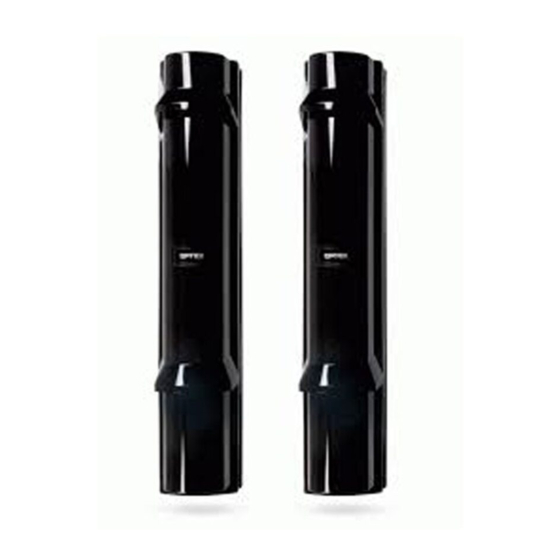
The transmitting unit (marked TRANSMITTER) and the receiving unit
(marked RECEIVER) are of identical mechanical construction.
Fig. 2 Barrier parts (identical for transmitter and receiver): A – Front barrier
cover, B – Main unit, C – Base of the unit, D – Rear cover, 1 – The locking
screw of the front cover, 2 – Viewfinder for barrier alignment, 3 – Optical part,
4 – Setting of optical viewing angle, 5 – Screws for main unit fixing,
6 – Battery holders, 7 – Jablotron transmitter
1. Unscrew the front cover screw (1) and remove it. Use a coin inserted
between the thresholds of the plastic parts to get it out and carefully take it
off by a prying motion.
2. Take away the main unit with the base (B+C) by releasing the 4 screws (5)
in the corner of the base unit (C). Then take the base of the unit away from
the rear cover (D).
3. Install the rear cover (D) onto the selected place, either directly onto a wall or
a post. On the rear plastic case holes are pre-pressed for installation on the
wall (WALL) or for a pole (POLE).
JA-151IR wireless 4beam optical barrier
JA-151IR wireless 4beam optical barrier
4. The Jablotron transmitter (7) and battery holders (6) are placed inside the
rear cover (D). Everything is connected to the main unit by a coloured wiring
harness with connectors. The connectors are unmistakable.
Enrolling the barrier transmitters into the
The radio transmitters for communication with the JABLOTRON 100
system are placed inside the rear cover (D) underneath the optical part of the
detector. The barrier occupies 2 positions in the system. Barrier activation is
reported by the receiving part of the barrier. Both barrier parts report
tampering and battery status.
For powering each unit always use a minimum of two SAFT LSH20
lithium batteries (they are included in the package). The correct position of
the batteries is marked inside the holder. Mind the correct polarity during
insertion. Four batteries can be inserted into the receiver and transmitter as
well. This prolongs the barrier operational time.
1. Enroll the radio transmitter to the system.
a. There must be a JA-110R radio module installed in the system.
b. Go to the F-Link software, select the required position in the Devices
window and launch the enrollment mode by clicking on the Enroll option.
c. Insert the batteries (mind the correct polarity). The enrollment signal is
transmitted when the first battery is inserted into the detector and the
device is enrolled to the selected position.
2. Screw on the base (C) and main (B) unit.
3. Do the barrier optical alignment according to the following chapter.
4. Screw on the cover and test the barrier functioning.
Fig. 3 Fig. 3 Radio transmitter (matched transmitter and receiver):
1 – terminals, 2 – option DIP switch (factory pre-set), 3 – external tamper
connector, 4 – external antenna jumper, 5 – external antenna connector
If needed the transmitter can be equipped with an AN-80 or AN-81
external antenna connected to the connector (5) and disconnect the
jumper (4).
Setting up the optical part of the barrier
Always perform the detector settings and beam alignment when the
tamper contact is blocked. The optical part of the barrier must be adjusted so
that the optical parts facing each other are physically aligned. Both units are
equipped with adjusting elements for the adjustment of direction and a view-
finder for precise adjustment. The unit opposite the one you want to adjust
must be in the centre of the aiming cross and the cross must be in the centre
of the view-finder (see fig. 4). There are optical covers placed inside the front
barrier covers. Slide the cover on the lower optical part and perform the
upper optical part setting then repeat the procedure for the lower part of the
optics. If it is needed to test the barrier function with a closed front cover it is
possible to lock the tamper contact by a rotating plate to avoid physical
closing of the barrier. The rotating plate is placed next to the tamper contact.
Fig. 4 Setting up the optical part
1 / 2
system
Receiver
N.C.
N.O.
Status (INP)
Pulse (INP)
AUX Fault
AUX Antimasking
Not used
Transmitter
N.C.
N.O.
Status (INP)
Pulse (INP)
AUX Fault
AUX Antimasking
Not used
Factory settings highlighted by bold letters.
MMY51902
Advertisement
Table of Contents

Subscribe to Our Youtube Channel
Related Manuals for jablotron JA-151IR


Summary of Contents for jablotron JA-151IR
- Page 1 JA-151IR wireless 4beam optical barrier The JA-151IR four-beam infra-red optical barrier is designed for the indication of 4. The Jablotron transmitter (7) and battery holders (6) are placed inside the a breach into a protected area by crossing the IR line between the transmitter and rear cover (D).
-
Page 2: Replacing The Batteries
EN 55022, EN 60950-1 Can be operated according to ERC REC 70-03 JABLOTRON ALARMS a.s. hereby declares that the JA-151IR module is in compliance with the essential requirements and other relevant provisions of Directive 1999/5/EC, 2011/65/EU. The original of the conformity assessment can be found at www.jablotron.com...
Need help?
Do you have a question about the JA-151IR and is the answer not in the manual?
Questions and answers