
Related Manuals for Dell EMC PowerEdge C6525


Summary of Contents for Dell EMC PowerEdge C6525
- Page 1 Dell EMC PowerEdge C6525 Installation and Service Manual Regulatory Model: E63S Series Regulatory Type: E63S001...
- Page 2 Notes, cautions, and warnings NOTE: A NOTE indicates important information that helps you make better use of your product. CAUTION: A CAUTION indicates either potential damage to hardware or loss of data and tells you how to avoid the problem. WARNING: A WARNING indicates a potential for property damage, personal injury, or death.
-
Page 3: Table Of Contents
Network ports indicator codes............................8 Locating the Express Service Code and Service Tag....................... 9 System information label..............................10 3 Initial system setup and configuration for PowerEdge C6525............13 Setting up the system................................. 13 iDRAC configuration................................13 Options to set up iDRAC IP address..........................13 Options to log in to iDRAC............................ - Page 4 Upgrading the Trusted Platform Module........................78 Initializing TPM for users...............................79 Initializing the TPM 1.2 for users..........................79 Initializing the TPM 2.0 for users..........................80 6 Jumpers and connectors for PowerEdge C6525................81 System board connectors..............................81 System board jumper settings............................82 Disabling a forgotten password............................82...
- Page 5 System diagnostic controls............................95 9 Getting help..........................96 Recycling or End-of-Life service information........................96 Contacting Dell..................................96 Accessing system information by using QRL........................96 Quick Resource Locator for PowerEdge C6525 system..................97 Receiving automated support with SupportAssist ......................97 10 Documentation resources......................98 Contents...
-
Page 6: About This Document
About this document This document provides an overview about the system, information about installing and replacing components, technical specifications, diagnostic tools, and guidelines to be followed while installing certain components. About this document... -
Page 7: Dell Emc Poweredge C6525 Overview
Dell EMC PowerEdge C6525 overview The PowerEdge C6525 is a half-width sled that supports: • Two AMD EPYC 7002 series processor • 16 DIMM slots The sled also supports PCIe and Open Compute Project (OCP) risers for expansion and connectivity. -
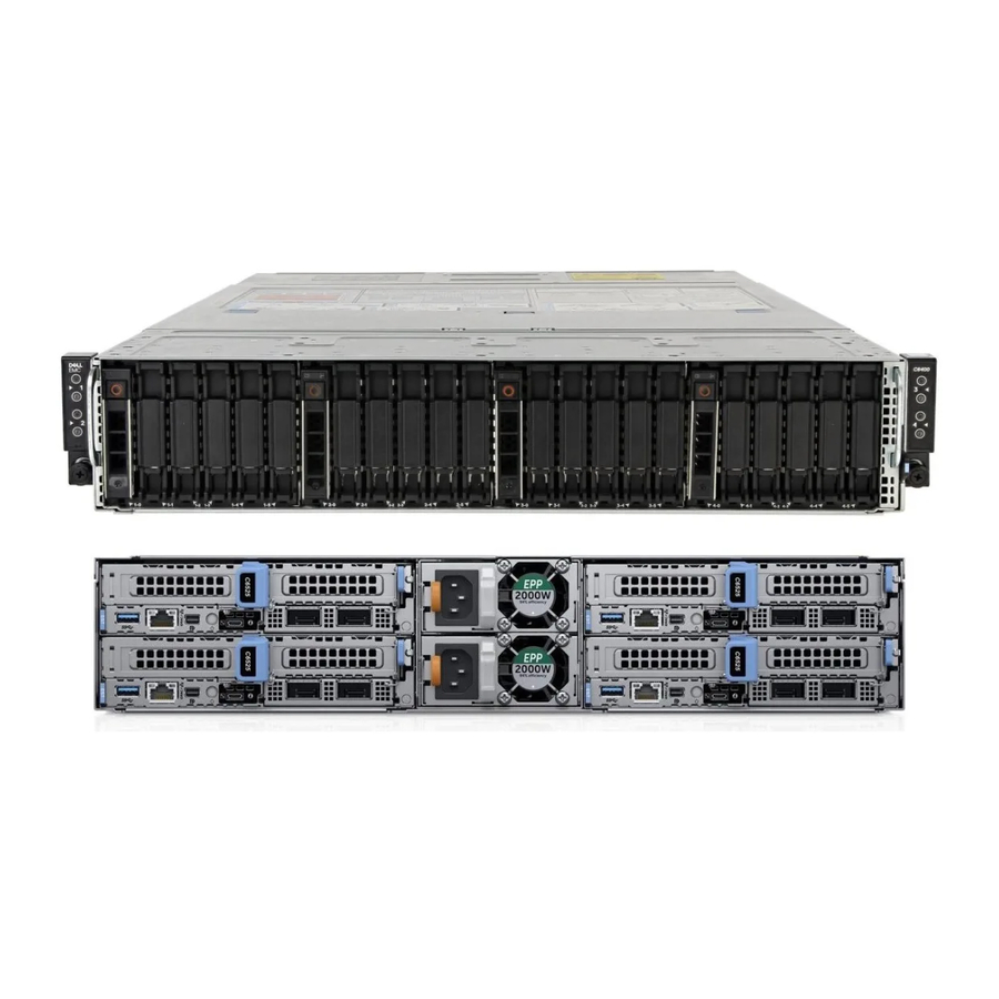
Page 8: Rear View Of The Sled
QSFP Lower green LED No link/Not Connected InfiniBand Physical Link - No Logical Link Green InfiniBand Logical Link - No Traffic Green Green InfiniBand Logical Link - Traffic Green Blink InfiniBand Physical Link Issue Blink Green Dell EMC PowerEdge C6525 overview... -
Page 9: Locating The Express Service Code And Service Tag
OpenManage Mobile (OMM) label, where administrators can configure, monitor, and troubleshoot the PowerEdge servers. Figure 5. Locating the Service Tag of your system 1. Information tag (top view) 2. Express Service Tag label 3. Network MAC address information label 4. iDRAC MAC address information label Dell EMC PowerEdge C6525 overview... -
Page 10: System Information Label
The Mini Enterprise Service Tag (MEST) label is located on the rear of the system that includes Service Tag (ST), Express Service Code (Exp Svc Code), and Manufacture Date (Mfg. Date). The Exp Svc Code is used by Dell EMC to route support calls to the appropriate personnel. - Page 11 Figure 7. Mechanical overview Figure 8. Memory information Dell EMC PowerEdge C6525 overview...
- Page 12 Figure 9. Jumper settings Figure 10. System tasks Dell EMC PowerEdge C6525 overview...
-
Page 13: Initial System Setup And Configuration For Poweredge C6525
The Integrated Dell Remote Access Controller (iDRAC) is designed to make you more productive as a system administrator and improve the overall availability of Dell EMC servers. iDRAC alerts you to system issues, helps you to perform remote management, and reduces the need for physical access to the system. -
Page 14: Options To Log In To Idrac
> Product Support page of your system > Manuals & documents. NOTE: To determine the most recent iDRAC release for your platform and for latest documentation version, see KB article at www.dell.com/support/article/sln308699. Initial system setup and configuration for PowerEdge C6525... -
Page 15: Options To Download Firmware
Remote Access Controller User's Guide, go to www.dell.com/ poweredgemanuals > Product Support page of your system > Manuals & documents. NOTE: To determine the most recent iDRAC release for your platform and for latest documentation version, see www.dell.com/support/article/sln308699. Initial system setup and configuration for PowerEdge C6525... -
Page 16: Downloading Drivers And Firmware
Steps 1. Go to www.dell.com/support/drivers. 2. Enter the Service Tag of the system in the Enter a Dell Service Tag, Dell EMC Product ID or Model field, and then press Enter. NOTE: If you do not have the Service Tag, select Detect PC to automatically detect the Service Tag, or click Browse all products, and navigate to your product. -
Page 17: Pre-Operating System Management Applications For Poweredge C6525
For more information about this utility, see Integrated Dell Remote Access Controller User’s Guide at www.dell.com/poweredgemanuals. Device Settings Enabled you to configure device settings for devices such as storage controllers or network cards. Pre-operating system management applications for PowerEdge C6525... -
Page 18: System Bios
Specifies the contact information of the system manufacturer. System CPLD Version Specifies the current version of the system complex programmable logic device (CPLD) firmware. UEFI Compliance Version Specifies the UEFI compliance level of the system firmware. Pre-operating system management applications for PowerEdge C6525... -
Page 19: Processor Settings
Specifies the MADT Core Enumeration. This option is set to Linear by default. NUMA Nodes Per Socket Specifies the number of NUMA nodes per socket. This option is set to 1 by default. Pre-operating system management applications for PowerEdge C6525... - Page 20 AHCI Mode. This option is set to Enabled by default. Write Cache Enables or disables the command for the embedded SATA drives during POST. This option is set to Disabled by default. Pre-operating system management applications for PowerEdge C6525...
-
Page 21: Boot Settings
Enables or disables the generic USB boot placeholder. This option is set to Disabled by default. Hard-disk Drive Placeholder Enables or disables the Hard-disk drive placeholder. This option is set to Disabled by default. Pre-operating system management applications for PowerEdge C6525... -
Page 22: Network Settings
Network Settings. NOTE: For information about Linux network performance settings, see the Linux Network Tuning Guide for AMD EPYC Processor Based Servers at AMD.com. NOTE: Network Settings are not supported in BIOS boot mode. Pre-operating system management applications for PowerEdge C6525... - Page 23 Specifies the secondary DNS server IP address for the HTTP Device. Obtain URI from the DHCP server if not specified Table 20. UEFI iSCSI Settings screen details Option Description iSCSI Initiator Name Specifies the name of the iSCSI initiator in IQN format. Pre-operating system management applications for PowerEdge C6525...
- Page 24 BIOS will output displays to both the primary add-in video and the embedded video during POST and pre-boot environment. The embedded video will then be disabled right before the operating system boots. This option is set to Enabled by default. Pre-operating system management applications for PowerEdge C6525...
- Page 25 NOTE: You can use only Serial Device 2 for the Serial Over LAN (SOL) feature. To use console redirection by SOL, configure the same port address for console redirection and the serial device. Pre-operating system management applications for PowerEdge C6525...
- Page 26 Set the system determinism by Power Determinism or Performance Determinism. This option is set to Power Determinism by default. Efficiency Optimized Mode Efficiency Optimized Mode maximizes Performance-per-Watt by opportunistically reducing frequency/power. Enables or disables the Efficiency Optimized Mode. Pre-operating system management applications for PowerEdge C6525...
-
Page 27: System Security
Enables or disables the power button on the front of the system. This option is set to Enabled by default. AC Power Recovery Sets how the system behaves after AC power is restored to the system. This option is set to Last by default. Pre-operating system management applications for PowerEdge C6525... - Page 28 Key (KEK) Database. Database Authorized Imports, exports, deletes, or restores entries in the Authorized Signature Signature Database (db). Database Forbidden Imports, exports, deletes, or restores entries in the Forbidden Signature Signature Database (dbx). Database Pre-operating system management applications for PowerEdge C6525...
-
Page 29: Using Your System Password To Secure Your System
1. To enter System Setup, press F2 immediately after turning on or restarting your system. 2. On the System Setup Main Menu screen, click System BIOS > System Security. 3. On the System Security screen, ensure that Password Status is set to Unlocked. Pre-operating system management applications for PowerEdge C6525... - Page 30 When set to Enabled, BIOS boots to the device specified in Redundant OS Location. When set to Disabled, BIOS preserves the current boot list settings. This option is set to Enabled by default. Pre-operating system management applications for PowerEdge C6525...
-
Page 31: Idrac Settings Utility
Certain platform configurations may not support the full set of features provided by the Dell Lifecycle Controller. For more information about setting up the Dell Lifecycle Controller, configuring hardware and firmware, and deploying the operating system, see the Dell Lifecycle Controller documentation at www.dell.com/idracmanuals. Pre-operating system management applications for PowerEdge C6525... -
Page 32: Boot Manager
To access the PXE boot option, boot the system and then press F12 during POST instead of using standard Boot Sequence from BIOS Setup. It does not pull any menu or allows managing of network devices. Pre-operating system management applications for PowerEdge C6525... -
Page 33: Installing And Removing System Components For Poweredge C6525
Steps 1. Install the sled into the enclosure. 2. Reconnect the peripherals and connect the system to the electrical outlet. 3. Power on the attached peripherals and then power on the system. Installing and removing system components for PowerEdge C6525... -
Page 34: Recommended Tools
Mixing of sled models in a system is not supported. Do not install predecessor sled models with the PowerEdge C6525 sled. CAUTION: Ensure that the chassis does not have a mixed architecture of PowerEdge C6420 and PowerEdge C6525 sled configurations. NOTE: Ensure to install a sled blank in all the empty slots. -
Page 35: Removing A Sled
Press the retention latch and holding the sled handle, pull the sled out of the enclosure. CAUTION: Ensure that the sled is supported with both hands while it is being slid out. Installing and removing system components for PowerEdge C6525... -
Page 36: Installing A Sled
Slide the sled into the enclosure until the retention lock clicks into place. NOTE: To avoid any damages to the pins on the sled, do not force the sled into the enclosure. Installing and removing system components for PowerEdge C6525... -
Page 37: Air Shroud
3. If applicable, disconnect the PERC battery cable from the connector on the system board. Steps 1. Press the blue clip and lift the air shroud. 2. Disengage the air shroud hook from the slot on the chassis and remove the air shroud. Installing and removing system components for PowerEdge C6525... -
Page 38: Installing The Air Shroud
Ensure that the SATA cables are routed behind the air shroud clip. NOTE: Route the cable properly to prevent the cable from being pinched or crimped. 2. Lower the air shroud until the blue clip locks in place. Installing and removing system components for PowerEdge C6525... -
Page 39: System Memory
Table 34. Memory population rules Processor Configuration Memory population Memory population information Single processor Optimizer (Independent A{1}, A{2}, A{3}, A{4}, A{5}, A{6}, Odd amount of DIMMs per channel) population order A{7}, A{8} processor allowed. Installing and removing system components for PowerEdge C6525... - Page 40 Table 35. NPS options per processor SKU or down core configuration Cores CCDs x CCXs x Cores/CCX NPSx options - Single NPSx options - Dual processor processor 8x2x4 4, 2, 1 4, 2, 1, 0 Installing and removing system components for PowerEdge C6525...
- Page 41 4 channel configuration of (CS C, D, G, H) but does not have optimal performance. • Requires all populated channels in a socket to have equal size memory. • In a dual processor system: Installing and removing system components for PowerEdge C6525...
-
Page 42: System Memory Guidelines
SKU. System memory guidelines The PowerEdge C6525 system supports DDR4 registered DIMMs (RDIMMs) and load reduced DIMMs (LRDIMMs). System memory holds the instructions that are executed by the processor. Your system contains 16 memory sockets organized into 8 channels per processor. -
Page 43: Removing A Memory Module
You must insert both ends of the memory module simultaneously. 2. Open the ejectors on the memory module socket outward to allow the memory module to be inserted into the socket. Installing and removing system components for PowerEdge C6525... -
Page 44: Support Bracket
1. Follow the safety guidelines listed in Safety instructions. 2. Follow the procedure listed in Before working inside your system. Steps 1. Using the Phillips #1 screwdriver, remove the screws that secure the support bracket to the chassis. Installing and removing system components for PowerEdge C6525... -
Page 45: Installing The Support Bracket
Steps 1. Align the support bracket with the stand off on the chassis. 2. Using a Phillips #1 screwdriver, secure the support bracket to the chassis. Figure 20. Installing the support bracket Installing and removing system components for PowerEdge C6525... -
Page 46: Expansion Cards
1. Using a Phillips #1 screw driver, remove the screws that secure the expansion card riser 1. 2. Holding the blue touch point, remove the expansion card riser from the chassis. Figure 21. Removing the expansion card riser 1 Next steps Install the expansion card riser Installing and removing system components for PowerEdge C6525... -
Page 47: Installing The Expansion Card Riser 1
Commission (FCC) certification of the system. The brackets also keep dust and dirt out of the system and aid in proper cooling and airflow inside the system. 1. Follow the safety guidelines listed in Safety instructions. 2. Follow the procedure listed in Before working inside your system. Remove the expansion card riser Installing and removing system components for PowerEdge C6525... -
Page 48: Installing The Expansion Card Riser 2
1. Align the screw holes on the riser with the stand offs on the system board and insert it until the riser card is firmly seated in the slot.. 2. Using a Phillips #1 screwdriver, tighten the screws that secure the expansion card riser 2. Installing and removing system components for PowerEdge C6525... -
Page 49: Removing An Expansion Card
Install an expansion card filler bracket over an empty expansion slot to maintain Federal Communications Commission (FCC) certification of the system. The brackets also keep dust and dirt out of the system and aid in proper cooling and airflow inside the system. Installing and removing system components for PowerEdge C6525... - Page 50 Figure 25. Removing an expansion card from riser 1 Figure 26. Installing the expansion card filler bracket in riser 1 Installing and removing system components for PowerEdge C6525...
- Page 51 Figure 27. Removing an expansion card from riser 2 Installing and removing system components for PowerEdge C6525...
-
Page 52: Installing An Expansion Card
2. Holding the card by its edges, align the card with the slot on the riser. 3. Insert the card until it is fully seated in the slot. 4. Replace the screw that secures the expansion card. Installing and removing system components for PowerEdge C6525... - Page 53 Figure 29. Removing the expansion card filler bracket Figure 30. Installing an expansion card in riser 1 Installing and removing system components for PowerEdge C6525...
- Page 54 Figure 31. Removing the expansion card filler bracket Installing and removing system components for PowerEdge C6525...
-
Page 55: Removing The Riser Card
5. If applicable, disconnect the cable from the riser card. Steps 1. Using a Phillips #2 screwdriver, remove the screws that secure the riser card to the expansion card riser. 2. Remove the riser card from the expansion card riser. Installing and removing system components for PowerEdge C6525... - Page 56 Figure 33. Removing the riser card from riser 1 Figure 34. Removing the riser card from riser 2 Next steps Install the riser card. Installing and removing system components for PowerEdge C6525...
-
Page 57: Installing The Riser Card
1. Align and insert the riser card with the screw holes on the riser. 2. Using a Phillips #2 screwdriver, tighten the screws that secure the riser card to the expansion card riser. Figure 35. Installing the riser card in riser 1 Installing and removing system components for PowerEdge C6525... -
Page 58: M.2 Riser
1. Using a Phillips #2 screwdriver, loosen the screw that secures the riser to the chassis. 2. Lift the riser to disengage the riser from the connector on the system board. 3. Disconnect the data cable from the riser. Installing and removing system components for PowerEdge C6525... -
Page 59: Installing The M.2 Riser
2. Align the M.2 riser with the stand off on the system board and insert it until the card is firmly seated in the slot. 3. Using a Phillips #2 screwdriver, tighten the screw that secures the riser to the chassis. Figure 38. Installing the M.2 riser Next steps Replace the air shroud. Installing and removing system components for PowerEdge C6525... -
Page 60: M.2 Ssd Module
1. Align the M.2 SSD module at an angle with the connector on the M.2 riser. 2. Insert the M.2 SSD module until it is firmly seated in the connector on the M.2 riser. Installing and removing system components for PowerEdge C6525... -
Page 61: Linking Board And Pcie Cable
The procedure to remove the MB_B cable is similar to removing the MB_A cable. 3. If applicable, disconnect the M.2 riser data cable from the M.2 riser. 4. Using a Phillips #2 screwdriver, loosen the captive screws that secure the linking board to the chassis. Installing and removing system components for PowerEdge C6525... -
Page 62: Installing The Linking Board And Pcie Cable
2. Align the linking board connector with the screw holes on the chassis and using a Phillips #2 screw driver tighten the captive screws to secure the linking board cable connector to the chassis. 3. Connect the MB connectors to the connectors on the system board. Installing and removing system components for PowerEdge C6525... -
Page 63: Processor And Heat Sink
Partially loosen the captive screws 2 and 1 (approximately 3 turns). c) Loosen the captive screws 4 and 3 completely. d) Loosen the captive screws 2 and 1 completely. 2. Lift the heat sink from the system. Installing and removing system components for PowerEdge C6525... -
Page 64: Removing The Processor
Remove the air shroud. Remove the heat sink. Steps 1. Using a Torx #T20 screwdriver, loosen the screws to release the force plate. The sequence to loosen the screws is 3, 2, and 1. Installing and removing system components for PowerEdge C6525... - Page 65 3. Holding the blue tab on the processor tray, slide the tray out of the rail frame. CAUTION: The processor socket pins are fragile and can be permanently damaged. Ensure not to bend the pins in the processor socket while handling the processor. Installing and removing system components for PowerEdge C6525...
-
Page 66: Installing The Processor
The thermal grease syringe is intended for single use only. Dispose the syringe after you use it. Steps 1. Holding the blue tab on the processor tray, slide the tray into the processor socket rail frame until firmly seated. Installing and removing system components for PowerEdge C6525... - Page 67 The three screws are tightened to a torque value of 12.0 ± 1.0 lbf-in. NOTE: Press the force plate while tightening the screws to avoid tilting of the processor cover out of the processor socket. Installing and removing system components for PowerEdge C6525...
-
Page 68: Installing The Heat Sink
Applying too much thermal grease can result in excess grease coming in contact with and contaminating the processor socket. NOTE: The thermal grease syringe is intended for one-time use only. Dispose the syringe after you use it. Installing and removing system components for PowerEdge C6525... - Page 69 Figure 51. Installing the heat sink 5. Return to the first screw to tighten it. Next steps Install the air shroud. 2. Follow the procedure listed in the After working inside your system. Installing and removing system components for PowerEdge C6525...
-
Page 70: Ocp Cards
1. Slide the OCP card and push until it is firmly connected to the system board connector. NOTE: Ensure to lift the OCP card retention latch if it is in the lock position. Installing and removing system components for PowerEdge C6525... -
Page 71: Removing An Ocp Card
Install an expansion card filler bracket over an empty expansion slot to maintain Federal Communications Commission (FCC) certification of the system. The brackets also keep dust and dirt out of the system and aid in proper cooling and airflow inside the system. Installing and removing system components for PowerEdge C6525... -
Page 72: Installing The Ocp Card Filler
2. Follow the procedure listed in Before working inside your system. Remove the expansion card riser Remove the expansion card riser Steps Align and insert the OCP filler until it is firmly seated. Installing and removing system components for PowerEdge C6525... -
Page 73: System Battery
To avoid damage to the battery holder clip, ensure that you do not bend the battery holder clip while installing or removing a battery. 2. Pull the battery out of the battery holder. NOTE: Ensure that the + side of the battery is facing the battery holder clip. Installing and removing system components for PowerEdge C6525... - Page 74 To test the newly installed battery, remove the system from the enclosure for at least an hour. e. Reinstall the system into the enclosure after an hour. f. Enter the System Setup and if the time and date are still incorrect, see Getting help section. Installing and removing system components for PowerEdge C6525...
-
Page 75: System Board
3. To disengage the ports from the slots on the chassis, push the system board to the front of the chassis. 4. Hold the system board by the edges and lift it at an angle and remove it from the chassis. Installing and removing system components for PowerEdge C6525... -
Page 76: Installing The System Board
1. Holding the system board by the edges and insert it at an angle and install it into the chassis. 2. To engage the ports with the slots on the chassis, push the system board to the rear of the chassis. Installing and removing system components for PowerEdge C6525... - Page 77 Re-enable the Trusted Platform Module (TPM). For more information, see the Upgrading the Trusted Platform Module section. 6. Import your new or existing iDRAC Enterprise license. For more information, see iDRAC User's Guide, at www.dell.com/idracmanuals. Installing and removing system components for PowerEdge C6525...
-
Page 78: Trusted Platform Module
Once the TPM plug-in module is installed, it is cryptographically bound to that specific system board. Any attempt to remove an installed TPM plug-in module breaks the cryptographic binding, the removed TPM cannot be reinstalled or installed on another system board. Installing and removing system components for PowerEdge C6525... -
Page 79: Initializing Tpm For Users
2. On the System Setup Main Menu screen, click System BIOS > System Security Settings. 3. From the TPM Security option, select On with Preboot Measurements. 4. From the TPM Command option, select Activate. 5. Save the settings. 6. Restart your system. Installing and removing system components for PowerEdge C6525... -
Page 80: Initializing The Tpm 2.0 For Users
1. While booting your system, press F2 to enter System Setup. 2. On the System Setup Main Menu screen, click System BIOS > System Security Settings. 3. From the TPM Security option, select On. 4. Save the settings. 5. Restart your system. Installing and removing system components for PowerEdge C6525... -
Page 81: Jumpers And Connectors For Poweredge C6525
CPLD Diagnostic LED / OmniVu System board diagnostic LED indicators Decoder MB_PWR PCIe Riser 2A Power Connector CPU1 Processor socket 1 A3, A4, A7, A8 Memory module sockets for CPU 1 CPU2 Processor socket 2 Jumpers and connectors for PowerEdge C6525... -
Page 82: System Board Jumper Settings
1. Power off the system, and all the attached peripherals, and disconnect the system from the electrical outlet. 2. Remove the system cover. 3. Move the jumper on the system board from pins 1 and 2 to pins 2 and 3. Jumpers and connectors for PowerEdge C6525... - Page 83 8. Move the jumper on the system board from pins 2 and 3 to pins 1 and 2. 9. Replace the system cover. 10. Reconnect the system to the electrical outlet and power on the system, and all the attached peripherals. 11. Assign a new system and/or setup password. Jumpers and connectors for PowerEdge C6525...
-
Page 84: Technical Specifications
• Video specifications • Environmental specifications Sled dimensions Figure 63. Sled dimensions Table 41. Dimensions of the PowerEdge C6525 sled 174.4 mm (6.86 inches) 40.1 mm (1.58 inches) 570.34 mm (22.45 inches) Chassis weight Table 42. Chassis weight with sleds... -
Page 85: Processor Specifications
41.5 kg (91.49 lb) System with no backplane 35.15 kg (77.49 lb) Processor specifications The PowerEdge C6525 sled supports up to two processors in each of the four independent sleds. Each processor supports up to 64 cores. Table 43. Processor specifications Supported processor Number of processors supported AMD EPYC™... -
Page 86: Memory Specifications
128 GB 1024 GB Drives specifications The PowerEdge C6525 sled supports SAS and SATA hard drives and Solid State Drives (SSDs). Table 46. Supported drive options for the PowerEdge C6525 sled Maximum number of drives in the Maximum number of drives assigned per sled sled 12 x 3.5-inch drive systems... -
Page 87: Ports And Connectors Specifications
The PowerEdge C6525 sled supports one Mini display port. NIC ports specifications The PowerEdge C6525 sled supports one 10/100/1000 Mbps Network Interface Controller (NIC) port located on the rear of the sled. iDRAC9 port specifications The PowerEdge C6525 sled supports one iDRAC9 direct port that is located on the rear of the system. -
Page 88: Environmental Specifications
Datasheet located with the Manuals & Documents on www.dell.com/poweredgemanuals. Standard operating temperature specifications NOTE: 1. Not available: Indicates that the configuration is not offered by Dell EMC. 2. Not supported: Indicates that the configuration is not thermally supported. NOTE: All components including the DIMMs, communication cards, M.2 SATA, and PERC cards can be supported with sufficient thermal margin if the ambient temperature is equal to or below the maximum continuous operating temperature listed in these tables. - Page 89 Cores 24 x drives 16 x drives 8 x drives 4 x drives No BP 7262 7282 7252 7272 NOTE: • 85C Optics Transceiver is required for OCP cards • Additional thermal restrictions are required for 128GB LRDIMM and GPU configuration Table 52.
- Page 90 Cores 24 x drives 16 x drives 8 x drives 4 x drives No BP 7252 7272 Table 54. Maximum continuous operating temperature for dual processor with 3.5-inch Direct drive configuration - Liquid cooled Cores 12 x drives 8 x drives 4 x drives 7742 7702...
-
Page 91: Expanded Operating Temperature Specifications
Table 56. Maximum continuous operating temperature for single processor with 3.5-inch Direct drive configuration - Air cooled Cores 12 x drives 8 x drives 4 x drives 7742 7702 7542 7502 7402 7452 7352 7302 7262 7282 7252 7272 Expanded operating temperature specifications Table 57. -
Page 92: Relative Humidity Specifications
Particulate Specifications contamination Conductive dust Air must be free of conductive dust, zinc whiskers, or other conductive particles. NOTE: This condition applies to data center and non-data center environments. Corrosive dust Air must be free of corrosive dust. Residual dust present in the air must have a deliquescent point less than 60% relative humidity. NOTE: This condition applies to data center and non-data center environments. -
Page 93: Maximum Altitude Specifications
Maximum altitude specifications Table 63. Maximum altitude specifications Maximum altitude Allowable Operation Maximum Temperature Gradient (applies to 20°C in an hour* (36°F in an hour) and 5°C in 15 minutes (9°F in 15 minutes), 5°C both operation and non-operation) in an hour* (9°F in an hour) for tape hardware Non-Operational Temperature Limits -40 to 65°C (-40 to 149°F) Non-Operational Humidity Limits... -
Page 94: Using System Diagnostics
Using system diagnostics If you experience a problem with your system, run the system diagnostics before contacting Dell for technical assistance. The purpose of running system diagnostics is to test your system hardware without using additional equipment or risking data loss. If you are unable to fix the problem yourself, service and support personnel can use the diagnostics results to help you solve the problem. -
Page 95: System Diagnostic Controls
System diagnostic controls Menu Description Configuration Displays the configuration and status information of all detected devices. Results Displays the results of all tests that are run. System health Provides the current overview of the system performance. Event log Displays a time-stamped log of the results of all tests run on the system. This is displayed if at least one event description is recorded. -
Page 96: Getting Help
Accessing system information by using QRL You can use the Quick Resource Locator (QRL) located on the information tag on the rear of the C6525 system, to access information about Dell EMC PowerEdge C6525. Prerequisites Ensure that your smartphone or tablet has the QR code scanner installed. -
Page 97: Quick Resource Locator For Poweredge C6525 System
Receiving automated support with SupportAssist Dell EMC SupportAssist is an optional Dell EMC Services offering that automates technical support for your Dell EMC server, storage, and networking devices. By installing and setting up a SupportAssist application in your IT environment, you can receive the following benefits: •... -
Page 98: Documentation Resources
To view the document that is listed in the documentation resources table: • From the Dell EMC support site: 1. Click the documentation link that is provided in the Location column in the table. 2. Click the required product or product version. - Page 99 Dell OpenManage Essentials, see OpenManage Essentials the Dell OpenManage Essentials User’s Guide. For information about installing and using Dell www.dell.com/serviceabilitytools SupportAssist, see the Dell EMC SupportAssist Enterprise User’s Guide. For information about partner programs enterprise www.dell.com/openmanagemanuals systems management, see the OpenManage Connections Enterprise Systems Management documents.
Need help?
Do you have a question about the PowerEdge C6525 and is the answer not in the manual?
Questions and answers