Stryker 6082 RUGGED MX-PRO Manual
Ambulance cot
Hide thumbs
Also See for 6082 RUGGED MX-PRO:
- Operation manual (40 pages) ,
- Operation & maintenance manual (115 pages)

Related Manuals for Stryker 6082 RUGGED MX-PRO


Summary of Contents for Stryker 6082 RUGGED MX-PRO
- Page 1 Operations/ Medical Maintenance Manual Model 6082 Rugged ® MX-PRO R3 Important Information File in your For parts or technical maintenance assistance call records 800 327 0770 (option 2)
-
Page 2: Table Of Contents
Table of Contents Introduction Specifications ................Warning / Caution / Note Definition . - Page 3 Table of Contents Assembly Drawings and Parts Lists Cot Assembly ..............41−46 Base Assembly .
-
Page 4: Introduction
# Cot may be loaded from any height and a height limiting kit (p/n 6060−202) is available to limit the load height of the cot. Stryker reserves the right to change specifications without notice. The MX−PRO is designed to conform to the Federal Specification for the Star−of−Life Ambulance KKK−A−1822−D. -
Page 5: Warning / Caution / Note Definition
Introduction WARNING / CAUTION / NOTE DEFINITION The words WARNING, CAUTION and NOTE carry special meanings and should be carefully reviewed. WARNING Alerts the reader about a situation, which if not avoided, could result in death or serious injury. It may also describe potential serious adverse reactions and safety hazards. -
Page 6: Warranty
Î Î Î Î Î Î Î Î Î Î Î Î Î Î Î Î Î Î Î Î Î Î Î Î Î Î Î Î Î Î Î Î Î Î One (1) year parts and labor. Under this option, Stryker EMS warrants to the original Î... - Page 7 Î Î Î Î Î Î Î Î Î Î Î Î Î Î Î Î Î Î Î Î Î Î Î Î Î Î Î Î Î Î Î Î Î Î CEIPT AT THE TIME OF RECEIPT. Upon prompt notification, Stryker will file a freight claim with the appropriate carrier for damages incurred.
-
Page 8: Summary Of Safety Precautions
Summary of Safety Precautions The following is a list of safety precautions that must be observed when operating or servicing this unit. The precautions are repeated throughout the manual, where applicable. Carefully read this list before using or servicing the unit. WARNING S Improper usage of the Cot can cause injury to the patient or operator. - Page 9 Modifying the cot will also void its warranty. CAUTION S Height limit kit is recommended for ambulance deck heights less than 30 inches (76 cm) − Stryker part number 6091−202−000. S Damage to the cot can occur if the cot is lowered in the shortened position. Use only positions 5−7 (see page 14) when the cot is shortened.
- Page 10 Notes...
-
Page 11: Set−Up Procedures
S Does the vehicle safety hook engage the safety bar so that the cot loads and unloads easily from the ve- hicle? S Is there an approved crash−stable fastener (Stryker part number 6370/6374/6377/6378 or 6371/6375 − not included) installed in the vehicle? -
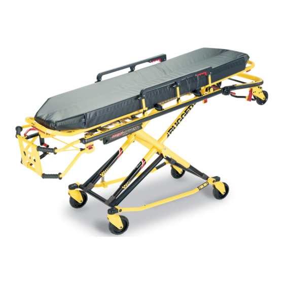
Page 12: Component Identification
Lifting Bar Foot Rest Release Handle Transport Wheels Wheel Lock (Optional) Figure 2 − 6082 MX−PRO R3 Cot Transport Wheels Long Safety Hook Short Safety Hook Stryker part number Stryker part number 6060−036−018 6060−036−017 J Safety Hook Stryker part number 6092−036−018... -
Page 13: Vehicle Safety Hook Installation
KKK−A−1822, revision E. " 2 CAUTION Height limit kit is recommended for ambulance deck heights less than 30 inches (76 cm) − Stryker part number 6091−202−000. Figure 3b − Ambulance Configuration Installation of the safety hook should be done by a certified mechanic familiar with ambulance construction. - Page 14 Hook (Not Supplied) 1/8 inch (2) Grade 5, 1/4”−20 Socket Head Cap Screws* (reference only) (Stryker part number 6060−36−17 & 6060−36−18) (2) Grade 5, 1/4”−20 Flat Socket Head Cap Screws* (Stryker part number 6092−36−18) (2) Flat Washers (2) Lock Washers (2) 1/4”−20 Nuts...
-
Page 15: Cot Positions
Cot Positions Position 1 − Use for patient transfer. Position 6 − Use for patient transfer/cot rolling. Position 2 − Use for patient transfer/cot rolling. Position 3 − Use for patient transfer/cot rolling. Position 7 − Use for patient transfer/cot rolling. Position 4 −... -
Page 16: Using Restraint Straps
Cot Operation Using Restraint Straps Figure 6 − Safety Restraints Figure 7 − Head Section Restraints Figure 8 − Foot Section Restraints WARNING Always use all restraint straps to secure the patient on the cot. An unrestrained patient may fall from the cot and be injured. - Page 17 Cot Operation Using Restraint Straps (Continued) Figure 9 − Buckling the Safety Restraints Figure 10 − Lengthening the Safety Restraint Figure 11 − Shortening the Safety Restraint When the cot is put into service, the restraints are opened and placed to either side of the cot until the patient is positioned on the cot mattress.
-
Page 18: Optional Pedi−Matet Instructions
Pedi−Matet Infant Restraint System Attachment Instructions Refer to the Pedi−Matet users manual for the manufacturer’s recommendations for the use, operation and care of the Pedi−Matet Infant Restraint System. Securing the Pedi−Matet to the cot 1. Remove any restraints already attached to the cot. 2. - Page 19 These are general instructions for installation of the Pedi−Matet. Safe and proper use of the Pedi−Matet is solely at the discretion of the user. Stryker recommends all users be trained on the proper use of the Pedi−Matet before using it in an actual situation.
-
Page 20: Transferring The Patient To The Cot
Cot Operation Operating Guidelines S Use the Cot only as described in this manual. S Read all labels and instructions on the cot before using the cot. S Use a minimum of two operators to manipulate the cot while a patient is on the cot. S Do not adjust, roll or load the cot without advising the patient. -
Page 21: Loading The Cot Into A Vehicle
Cot Operation Loading the Cot into a Vehicle with Two Operators When loading the cot into a vehicle, an operator should remember the following important issues: S Two operators must be present when the cot is occupied. S There must be a safety hook properly installed in the vehicle so that the bumper does not inter- fere with the front legs of the base frame. -
Page 22: Loading An Empty Cot Into A Vehicle
Cot Operation Loading an Empty Cot into a Vehicle with One Operator WARNING This procedure is for use only with an empty cot. Do not use this procedure when loading a patient. Inju- ry to the patient and/or operator could result. 1. -
Page 23: Unloading The Cot From A Vehicle
Cot Operation Unloading the Cot from a Vehicle with Two Unloading an Empty Operators from a Vehicle with One Operator 1. Disengage the cot from the cot fastener. (For more detailed instructions, reference the cot WARNING fastener installation/operation manual − Stryk- This procedure is for use only with an empty cot. -
Page 24: Using Additional Assistance
Cot Operation USING ADDITIONAL ASSISTANCE Rolling Loading/Unloading Changing Levels Helper Helper Helper Helper Operators Helpers Operator Operator Operator Operator Operator Helper Helper Operator Helper Helper Helper Helper Helper Operator Helper Helper Operators Helper Four Helpers Operator Operator Operator Helper Operator Helper Helper Helper... -
Page 25: Operating Optional Wheel Lock
Cot Operation OPERATING THE OPTIONAL WHEEL LOCK(S) Figure 22 − RuggedR Wheel Lock 1. To activate the optional wheel lock(s), press fully down on the pedal (A) until it stops. 2. To release the optional wheel lock(s), depress the upper face of the pedal with your foot or lift up with your toe under the pedal. -
Page 26: Adjusting The Wheel Locking Force
Cot Operation ADJUSTING THE WHEEL LOCKING FORCE MINIMUM MAXIMUM Figure 23 − Wheel Locking Force Adjustment 1. To adjust the wheel locking force, remove the hex socket screw from the center of the lock pedal. The wheel lock is initially assembled with the pedal set at the minimum locking force. The marker on the pedal (item A) is aligned with the marker on the octagonal sleeve (item B). -
Page 27: Changing Cot Height With Two Operators
Cot Operation CHANGING COT HEIGHT WITH TWO OPERATORS FOOT END Figure 24 − Release Handle Locations NOTE Changing the height while a patient is on the cot requires a minimum of two operators, positioned at both ends or on each side of the cot. Each operator must grasp the cot frame securely. To lower the cot from the ends, the operator at the foot end of the cot positions his/her hands so the release handle (A or B) can be squeezed while a secure grip is maintained on the lifting bars. -
Page 28: Changing The Height Of An Empty Cot
Cot Operation Changing the Height of an Empty Cot with One Operator To raise/lower the cot from the foot end: To raise/lower the cot from the side: 1. Standing at the foot end of the cot, grasp the 1. Place one foot on the outer base tube. lower foot end lift tube. -
Page 29: Adjusting Leg Rest
Cot Operation Adjusting the Leg Rest FOOT END Figure 29 − Leg Rest Elevated The leg rest is adjustable to allow for elevation of the patient’s legs. To raise the leg rest, lift the leg rest frame (A) as high as possible. The support bracket will engage automati- cally. -
Page 30: Operating Backrest
Cot Operation HEAD END Figure 30 − Backrest Elevated and Siderails Raised Operating the Backrest To raise, squeeze handle (A) for pneumatic assist in lifting the Backrest to the desired height. Remove hand(s) from handle when desired height is achieved. To lower, squeeze handle (A) and push down on the Backrest frame until the Backrest has reached the de- sired height. -
Page 31: Operating Breakaway Head Section
Cot Operation Operating the Breakaway Head Section Figure 31 − Breakaway Head Section Figure 32 − Lowered Breakaway Release Bar Head Section The head end of the cot litter folds down to shorten the length of the cot and allow for maneuvering when space is limited in elevators, halls, etc. -
Page 32: Operating I.v. Poles
Cot Operation Operating the 2−Stage I.V. Pole Figure 33 − 2−Stage I.V. Pole Storage Position Figure 34 − 2−Stage I.V. Pole 1. Lift and pivot the pole from the storage position and push down until it is locked into receptacle (A). 2. - Page 33 Cot Operation Operating the 3−Stage I.V. Pole (Optional Equipment) 1. Lift and pivot the pole from the storage position and push down until it is locked into receptacle (A). 2. To raise the height of the pole, turn the lock actuator (B) counter- clockwise and pull up on the bottom telescoping portion (C) of the pole to raise it to the desired height.
-
Page 34: Cleaning
Velcro should be determined by the hospital.) Washing Procedure: Follow the cleaning solution manufacturer’s dilution recommendations exactly. The preferred method Stryker Medical recommends for power washing the 6082 cot is with the standard hospital surgical cart washer or hand held wand unit. Washing Limitations: WARNING Use any appropriate personal safety equipment (goggles, respirator, etc.) to avoid the risk of inhaling conta-... - Page 35 SOME CLEANING PRODUCTS ARE CORROSIVE IN NATURE AND MAY CAUSE DAMAGE TO THE PRODUCT IF USED IMPROPERLY. If the products described above are used to clean the Stryker patient care equipment, measure must be taken to insure the cots are wiped with clean water and thoroughly dried following cleaning.
-
Page 36: Preventative Maintenance Schedule & Checklist
For 201+ calls per month, in- spect cot monthly. NOTE Keep up−to−date maintenance records using the form on page 39. Parts, Service or Technical Assistance: Contact Stryker Customer Service at 1−800−327−0770 or Stryker Medical 3800 E. Centre Ave. Portage, MI 49002 ATTN: Customer Service... -
Page 37: Base Lubrication
2. Turn the cot upside down with the base legs facing up. 3. Using the plastic applicator tube, spray Tri−Flowt with TeflonR lubricant (Stryker part number 6082−199−12) in the gap between the upper (item A) and lower lift tubes (item B) on both foot end legs. -
Page 38: Pneumatic Fowler Adjustment
Preventative Maintenance PNEUMATIC BACKREST ADJUSTMENT Required Tools: 1/2” Wrench 5/32” Allen Wrench Locktite 3/32” Allen Wrench Adjustment Procedure: 1. For easier access, move backrest to 75 degrees. NOTE Before continuing with the backrest adjustment procedure, be sure the cylinder (item A) is completely threaded into the yoke (item B) so no threads are showing on the shaft of the cylinder. - Page 39 Notes...
-
Page 40: Maintenance Record
Maintenance Record Date Maintenance Operation Performed... -
Page 41: Training Record
Training Record Training Date Training Method Trainee Name Basic Refresher Owner’s Manual, In−Service, Training Update Formal Class, Etc. -
Page 42: Cot Assembly
Cot Assembly... - Page 43 Cot Assembly DETAIL 2 DETAIL 1 RIGHT HAND RELEASE OPTION LEFT HAND RELEASE OPTION DETAIL 4 DETAIL 3 DETAIL 5...
- Page 44 Cot Assembly...
- Page 45 Cot Assembly...
- Page 46 Cot Assembly Item Part No. Part Name Qty. (page 47−50) Base Assembly (page 57) Litter/Base Adapter Ass’y, Right (page 58) Litter/Base Adapter Ass’y, Left 6082−205−60 Litter/Base Adapter Spacer Sleeve (page 59−64) Litter Assembly 4−135 Button Head Cap Screw 4−204 Button Head Cap Screw 6060−37−26 Pivot Spacer Plate 6060−37−35...
- Page 47 Cot Assembly 6080−300−10 Pedi−Matet Restraint Bracket Option Item Part No. Part Name Qty. 6080−32−60 Restraint Bracket 25−79 Rivet...
-
Page 48: Base Assembly
Base Assembly Assembly part number 6082−101−11 (reference only) - Page 49 Base Assembly DETAIL 1 OUTER TUBE DETAIL 2 INNER TUBE EXTENDED STANDARD HEIGHT HEIGHT OPTION OPTION...
- Page 50 Base Assembly FOOT END LEFT SIDE RELEASE OPTION FOOT END RIGHT SIDE RELEASE OPTION...
-
Page 51: Wheel Assembly
Base Assembly Item Part No. Part Name Qty. 6060−1−21 Caster Mount Cover 6060−1−30 Center Base Spacer 6060−1−31 Inner Base Spacer, Foot End 6060−1−32 Inner Base Spacer, Head End 6060−1−70 Upper Frame Tube Bearing 6060−1−71 Lower Frame Tube Bearing (page 51) Wheel Assembly 6060−5−29 Height Adj. - Page 52 6060−2−10 Wheel Assembly Item Part No. Part Name Qty. 81−226 Bearing 715−1−255 Wheel Bushing...
-
Page 53: Lift Tube Assembly
6082−1−67 Base Pivot Outer Lift Tube Assembly Item Part No. Part Name Qty. 25−79 Blind Rivet 6082−1−35 Dampener 6082−1−36 Dampener Sleeve 6082−1−57 Outer Lift Tube Weldment... - Page 54 6082−1−69 Base Pivot Inner Lift Tube Assembly Item Part No. Part Name Qty. 6082−1−59 Inner Lift Tube Weldment 25−79 Blind Rivet 6082−1−35 Dampener 6082−1−36 Dampener Sleeve...
-
Page 55: Lock Bar Assembly
6082−5−56 Height Adjustment Lock Bar Assembly Item Part No. Part Name Qty. 28−181 Retaining Ring 6082−5−55 Height Adj. Rack Lock Bar 6082−5−65 Lock Bar Slide Plate 6082−5−96 Height Adj. Rack Latch Pin 81−248 Bearing... -
Page 56: Wheel Lock Options
Wheel Lock Options 6082−500−10 No Wheel Lock Option Item Part No. Part Name Qty. 6082−2−12 Caster Horn 6082−501−10 Single Wheel Lock Option Item Part No. Part Name Qty. 6082−2−12 Caster Horn (page 56) Wheel Lock Ass’y 6082−502−10 Dual Wheel Lock Option Item Part No. -
Page 57: Wheel Lock Assembly
6082−200−10 Adjustable Wheel Lock Assembly Item Part No. Part Name Qty. 6082−100−12 Caster Horn 6080−100−32 Spring 11−456 Washer 25−153 Semi−Tubular Rivet 6080−90−101 Warning Label 6080−200−30 Adjustable Pedal 6080−200−41 Octagonal Sleeve 4−98 Hex Soc. But. Hd. Cap Screw 16−118 Centerlock Nut... -
Page 58: Litter/Base Adapter Assembly
6082−205−50 Litter/Base Adapter Assembly, Right Item Part No. Part Name Qty. 6082−5−34 Adapter Mounting Bracket, Rt. 6082−5−51 Adapter Pivot Tube 37−225 Hole Plug 25−79 Blind Rivet... - Page 59 6082−205−53 Litter/Base Adapter Assembly, Left Item Part No. Part Name Qty. 6082−5−35 Adapter Mounting Bracket, Lt. 6082−5−51 Adapter Pivot Tube 37−225 Hole Plug 25−79 Blind Rivet...
-
Page 60: Litter Assembly
Litter Assembly Assembly part number 6082−130−11 (reference only) SEE DETAIL 1 DETAIL 1... - Page 61 Litter Assembly DETAIL 3 DETAIL 2 DETAIL 4 TREND ASSEMBLY VIEW...
- Page 62 Litter Assembly DETAIL 5A Ensure Item AF is inserted .25” from surface to end of tube DETAIL 5B See Detail 5A DETAIL 5 DETAIL 6...
- Page 63 Litter Assembly 6082−700−19 Fowler Release Handle Kit DETAIL 7...
- Page 64 Litter Assembly...
- Page 65 Litter Assembly Item Part No. Part Name Qty. Item Part No. Part Name Qty. 721−31−65 Hole Plug 18−38 Umbrella Nut 938−1−177 Knob 21−119 Set Screw 946−35−25 Liner 21−138 Set Screw 6060−32−38 Gas Cylinder Yoke 25−132 Blind Rivet 6060−32−40 Fowler Lift Pivot 28−76 External Retaining Ring 6070−38−33...
- Page 66 Notes...
- Page 67 Lift Tube Assembly, Left Side Release Option Assembly part number 6082−40−59 (reference only) DETAIL 1...
- Page 68 Lift Tube Assembly, Left Side Release Option DETAIL 2 Item Part No. Part Name Qty. 25−79 Rivet 6082−140−30 Lift Brace 6082−140−53 Upper Lift Tube Assembly 6082−140−54 Lower Lift Tube Assembly 6080−40−12 End Cap 6082−130−38 Litter Stop 37−238 Hole Plug (page 70) Handle 6082−40−32 Spacer...
- Page 69 Lift Tube Assembly, Right Side Release Option Assembly part number 6082−40−60 (reference only) DETAIL 1...
- Page 70 Lift Tube Assembly, Right Side Release Option DETAIL 2 Item Part No. Part Name Qty. 25−79 Rivet 6082−140−30 Lift Brace 6082−40−57 Upper Lift Tube Assembly 6082−40−58 Lower Lift Tube Assembly 6080−40−12 End Cap 6082−130−38 Litter Stop 37−238 Hole Plug (page 70) Handle 6082−40−32 Spacer...
-
Page 71: Release Handle Assembly
6080−40−40 Release Handle Assembly Item Part No. Part Name Qty. 25−125 Rivet 6080−40−41 Release Handle Link 6080−40−50 Side Release Handle Ass’y... -
Page 72: Siderail Assembly
6082−26−10 Siderail Assembly Item Part No. Part Name Qty. 6060−25−24 Top Rail 6060−25−43 Spindle 6060−25−47 Spindle Lock 6060−25−41 Spindle Pivot 6060−25−40 Spindle Pivot Stop 6060−25−29 Lock Release Grip 6061−125−30 Lock Bar 38−344 Compression Spring 6060−25−35 Pivot Bushing 25−131 Rivet... -
Page 73: Breakaway Head Assembly
Breakaway Head Assembly Assembly part number 6080−37−10 (reference only) Item Part No. Part Name Qty. 14−67 Nylon Flat Washer 25−79 Rivet 28−138 Retaining Ring 6080−36−25 Pivot Pin 6080−36−47 Bent Release Crossbar (page 74) Breakaway Head Section 6082−37 Standard Height Option 6082−38 Extended Height Option Item Part No. - Page 74 Breakaway Head Assembly Assembly part number 6080−37−55 (reference only) DETAIL 1 DETAIL A See Detail A See Detail 1...
- Page 75 Breakaway Head Assembly Item Part No. Part Name Qty. Item Part No. Part Name Qty. 4−54 H. Soc. But. Hd. Cap Scr. 6060−36−24 Pivot Stop Pin 4−135 H. Soc. But. Hd. Cap Scr. 6060−37−21 Safety Hook Pivot 4−136 Pan Hd. Machine Screw 6060−37−26 Pivot Spacer Plate 4−163...
-
Page 76: Pole Mounting Assembly, Right
6080−210−10 Optional 2−Stage I.V. Mounting Ass’y, Rt. 6080−215−10 Optional 3−Stage I.V. Mounting Ass’y, Rt. 6080−210−10 6080−215−10 Item Part No. Part Name Qty. Item Part No. Part Name Qty. 6070−110−32 I.V. Retainer Plate 6070−110−32 I.V. Retainer Plate 6080−110−35 I.V. Clip 6080−110−35 I.V. Clip (page 76) 2−Stage I.V. -
Page 77: 2−Stage I.v. Assembly, Right
6080−210−20 2−Stage I.V. Assembly, Patient Right Item Part No. Part Name Qty. 6070−90−105 Caution Label (page 81) 2−Stage I.V. Pole Assembly 6070−210−45 I.V. Pole Sleeve 6070−210−46 I.V. Pivot 6070−210−49 I.V. Pivot Ring 6080−90−31 Specification Label 6080−210−52 I.V. Socket Weldment, Right 25−133 Rivet... -
Page 78: 3−Stage I.v. Assembly, Right
6080−215−20 3−Stage I.V. Assembly, Patient Right Item Part No. Part Name Qty. 6070−90−105 Caution Label 6070−210−45 I.V. Pole Sleeve 6070−210−46 I.V. Pivot 6070−210−49 I.V. Pivot Ring (page 82) 3−Stage I.V. Pole Assembly 6080−90−33 Specification Label 6080−210−52 I.V. Socket Weldment, Right 25−133 Rivet... -
Page 79: Pole Mounting Assembly, Left
6080−211−10 Optional 2−Stage I.V. Mounting Ass’y, Left 6080−216−10 Optional 3−Stage I.V. Mounting Ass’y, Left 6080−211−10 6080−216−10 Item Part No. Part Name Qty. Item Part No. Part Name Qty. 6070−110−32 I.V. Retainer Plate 6070−110−32 I.V. Retainer Plate 6080−110−35 I.V. Clip 6080−110−35 I.V. Clip (page 79) 2−Stage I.V. -
Page 80: 2−Stage I.v. Assembly, Left
6080−211−20 2−Stage I.V. Assembly, Patient Left Item Part No. Part Name Qty. 6070−90−105 Caution Label (page 81) 2−Stage I.V. Pole Assembly 6070−210−45 I.V. Pole Sleeve 6070−210−46 I.V. Pivot 6070−210−49 I.V. Pivot Ring 6080−90−32 Specification Label 6080−211−52 I.V. Socket Weldment, Left 25−133 Rivet... -
Page 81: 3−Stage I.v. Assembly, Left
6080−216−20 3−Stage I.V. Assembly, Patient Left Item Part No. Part Name Qty. 6070−90−105 Caution Label 6070−210−45 I.V. Pole Sleeve 6070−210−46 I.V. Pivot 6070−210−49 I.V. Pivot Ring (page 82) 3−Stage I.V. Pole Assembly 6080−90−34 Specification Label 6080−211−52 I.V. Socket Weldment, Left 25−133 Blind Rivet... -
Page 82: V. Pole Assembly
6070−210−40 2−Stage I.V. Pole Assembly Item Part No. Part Name Qty. 1210−110−46 Back−Up Ring 1210−110−47 Lock Ring 1210−110−49 Molded Actuator 6070−210−41 Base Tube 6070−110−42 2nd Stage Tube 6070−110−44 2nd Stage Slide Plug 6070−110−50 Hook Weldment 26−6 Roll Pin... - Page 83 6070−215−40 3−Stage I.V. Pole Assembly Item Part No. Part Name Qty. 1210−110−46 Back−Up Ring 1210−110−47 Lock Ring 1210−110−49 Molded Actuator 6070−210−41 Base Tube 6070−110−44 2nd Stage Slide Plug 6070−110−50 Hook Weldment (page 83) 3rd Stage Assembly 6070−115−42 2nd Stage Tube 6070−115−45 Bearing Plug 26−5...
- Page 84 6070−115−30 3rd Stage Ass’y − Optional 3−Stage I.V. Pole Item Part No. Part Name Qty. 6070−115−141 Spring Clip 6070−115−143 3rd Stage Tube 6070−115−44 3rd Stage Slide Plug 26−4 Roll Pin 45−139 O−Ring...
-
Page 85: Hanging Oxygen Bottle Holder Assembly
6080−140 Optional Hanging Oxygen Bottle Holder Ass’y Assembly part number 6080−140−10 (reference only) Item Part No. Part Name Qty. 6080−140−11 Bottle Holder Hanger 6080−140−12 Oxygen Bottler Holder... -
Page 86: Permanent Oxygen Bottle Holder Assembly, Foot End
6070−140 Optional Foot End Oxygen Bottle Holder Assembly part number 6070−140−10 (reference only) Item Part No. Part Name Qty. 25−79 Rivet 4−508 But. Hd. Cap Screw 6060−90−4 “Rugged” Label 6060−140−13 Strap Assembly (page 86) Bottle Holder Tray Ass’y 6070−90−14 Specification Label 6070−140−17 Support Bracket 16−111... -
Page 87: Foot End Bottle Holder Tray Assembly
6060−140−20 Foot End O2 Bottle Holder Tray Item Part No. Part Name Qty. 11−436 Flat Washer 25−133 Rivet 37−55 37−56 Washer 946−1−155 Bumper 6060−140−15 Bottle Holder Tray... -
Page 88: Permanent Oxygen Bottle Holder Assembly, Head End
6082−140−000 Optional Head End O2 Bottle Holder Item Part No. Part Name Qty. 4−197 Hex Soc. But. Hd. Cap Screw 16−102 Nylock Hex Nut 25−79 Blind Rivet (page 88) Tray Assembly 6082−140−43 Strap Assembly 6082−140−44 Fowler Handle Guard... -
Page 89: Head End Bottle Holder Tray Assembly
6082−140−40 Head End O2 Bottle Holder Tray Item Part No. Part Name Qty. 4−455 But. Hd. Cap Screw 11−52 Washer 11−436 Washer 16−28 Hex Nut 25−99 Dome Head Rivet 25−133 Dome Head Rivet 29−3 Brass Eyelet 37−55 Black Protective Cap 37−56 Retaining Washer 946−1−155... -
Page 90: Pull Handle Assembly
6080−155−20 Optional Pull Handle Assembly Item Part No Part Name Qty. 6080−255−1 Pull Handle Bracket, Left 6080−255−2 Pull Handle Bracket, Right 6080−255−3 Pull Handle 721−26−69 Upright Sleeve 25−79 Dome Hd. Rivet 4−130 Hex Soc. But. Hd. Cap Screw 16−36 Nylock Hex Nut... -
Page 91: Base Lift Bar Assembly
6080−157 Optional Base Lift Bar Assembly Item Part No. Part Name Qty. 4−135 Hex Soc. But. Hd. Cap Screw 16−28 Nylock Hex Nut 37−238 Tube Plug 6080−157−13 Breakaway Lift Bar Weldment... -
Page 92: Base Storage Tray Assembly
6082−150−15 Optional Base Storage Tray Item Part No. Part Name Qty. 6082−150−20 Base Storage Tray 25−79 Rivet... -
Page 93: Frame Guard Assembly
6082−700−14 X−Frame Guard Retrofit Kit HEAD END Item Part No. Part Name Qty. 6080−145−1 Upper Frame Guard 6080−145−2 Lower Frame Guard 16−3 Hex Nut 4−508 Button Hd. Cap Screw... -
Page 94: Retaining Post Options
6082−200 Patient Right Side Retaining Post Option Item Part No. Part Name Qty. 4−135 Button Head Cap Screw 4−503 Button Head Cap Screw 4−161 Button Head Cap Screw 721−31−65 Hole Plug 6060−4−43 Retaining Post Cap 6060−4−44 Retaining Post Tube 6080−4−45 Top Retaining Post Bracket 6080−4−46 Bottom Retaining Post Bracket... - Page 95 6082−190 Dual Retaining Post Option Item Part No. Part Name Qty. 4−135 Button Head Cap Screw 4−503 Button Head Cap Screw 4−161 Button Head Cap Screw 6060−4−43 Retaining Post Cap 6060−4−44 Retaining Post Tube 6080−4−45 Top Retaining Post Bracket 6080−4−46 Bottom Retaining Post Bracket...
- Page 96 6082−128−000 Optional Head End Storage Tray Item Part No. Part Name Qty. 4−197 Button Hd. Cap Screw 16−102 Nylock Nut (page 96) Tray Assembly...
-
Page 97: Head End Storage Tray
6082−128−20 Head End Storage Tray Item Part No. Part Name Qty. 6082−128−80 Breakaway Tray 6082−128−19 Adhesive Loop Pile 6081−91−57 Caution Label... -
Page 98: Head Extension Option
6100−700−012 Head Extension Option Kit 6100−044−000 Head Extension Option Item Part No. Part Name Qty. 6100−41−30 Head Extension Pillow 6100−44−12 Head Extension Assembly... - Page 99 6100−044−012 Head Extension Assembly Item Part No. Part Name Qty. 6100−−44−10 Bracket Weldment 6100−44−7 Support 6100−44−11 Extension Tube 6100−44−8 Pillow Support 6100−44−5 Insert 28−76−0 Clip 6100−44−6 Spacer 16−28−0 Nylock Nut 4−161−0 Button Head Cap Screw 4−232−0 Button Head Cap Screw 6372−10−16 Pull Pin Assembly 25−79−0...
-
Page 100: Backrest Pouch Option
6500−130−000 Backrest Pouch Option Item Part No. Part Name Qty. 6500−130−000 Backrest Pouch Option... -
Page 101: Restraint Strap Package
6082−260−10 Restraint Strap Package SHOULDER HARNESS ASSEMBLY REQUIRED 1 STRAP REQUIRED 2 STRAPS REQUIRED Item Part No. Part Name Qty. 6060−260−45 Four Point Harness 6060−160−44 Lap Belt 6082−160−51 Plastic Cap 6060−260−46 Chest Restraint Strap 37” 37” Fully Extended Fully Extended... -
Page 102: Storage Pouch Options
Head End Storage Pouch Options 28 1/2” 28 1/2” FRONT OF POUCH FRONT OF POUCH 32 3/8” 32 3/8” 20” 20” 6082−128−10 6082−128−12 Pouch with Pockets Flat Pouch 6082−160−52 Optional Accessory Strap 27 1/2” 27 1/2” Fully Extended Fully Extended... -
Page 103: Quick Reference Replacement Parts List
The parts and accessories listed on this page are all currently available for purchase. Some of the parts identi- fied on the assembly drawings pages in this manual may not be individually available for purchase. Please call Stryker Customer Service at 1−800−327−0770 for availability and pricing. ITEM... - Page 104 Quick Reference Replacement Parts List Restraint, Shoulder Harness ..........6060−260−45 Restraint Strap Plastic Cap .
- Page 105 European Representative Stryker EMEA RA/QA Director Stryker France ZAC Satolas Green Pusignan Av. De Satolas Green 69881 MEYZIEU Cedex France 3800 E. Centre Ave, Portage, MI 49002 (800) 327−0770 www.stryker.com JH 10/05 6082−090−014 REV F...
Need help?
Do you have a question about the 6082 RUGGED MX-PRO and is the answer not in the manual?
Questions and answers