Stryker Performance-PRO XT Operation & Maintenance Manual
Hide thumbs
Also See for Performance-PRO XT:
- Operation manual (54 pages) ,
- Maintenance manual (138 pages)

Related Manuals for Stryker Performance-PRO XT


Summary of Contents for Stryker Performance-PRO XT
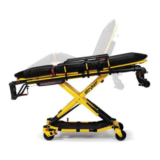
- Page 1 Performance-PRO™ XT Model 6086 Operations/Maintenance Manual For parts or technical assistance: USA: 1-800-327-0770 2012/05 B.0 6086-009-001 REV B www.stryker.com...
-
Page 3: Table Of Contents
Using the Restraint Belt Extension ............www.stryker.com... - Page 4 Caster Horn Assembly ..............6086-009-001 REV B www.stryker.com...
- Page 5 Three-Stage I.V. Pole Assembly, Right - 6500-215-000..........www.stryker.com...
- Page 6 Stryker EMS Return Policy ........
-
Page 7: Symbols And Definitions
NOTE Provides special information to make maintenance easier or important instructions clearer. Return To Table of Contents www.stryker.com 6086-009-001 REV B... -
Page 8: Introduction
Introduction This manual is designed to assist you with the operation and maintenance of the Stryker Performance-PRO™ XT cot. Read this manual thoroughly before using the equipment or beginning maintenance on it. To ensure safe operation of this equipment, it is recommended that methods and procedures be established for educating and training staff on the safe operation of this cot. -
Page 9: Specifications
The Performance-PRO™ XT is designed to conform to the Federal Specification for the Star-of-Life Ambulance (KKK-A-1822). The Performance-PRO™ XT is designed to be compatible with competitive cot fastener systems. Patents pending. The yellow and black color scheme is a proprietary trademark of Stryker Corporation. Return To Table of Contents www.stryker.com... -
Page 10: Contact Information
3800 E. Centre Avenue Portage, MI 49002 SERIAL NUMBER LOCATION Please have the serial number (Figure 1) of your Stryker product available when calling Stryker Customer Service or Technical Support. Include the serial number in all written communication. Head End Figure 1: Cot Serial Number &... -
Page 11: Product Illustration
Cot Retaining Post Foot End Transport Wheels Knee Gatch (Optional)) J Safety Hook Long Safety Hook Short Safety Hook Stryker part number Stryker part number Stryker part number 6092-036-018 6060-036-018 6060-036-017 Figure 2: Cot Components Return To Table of Contents www.stryker.com... -
Page 12: Summary Of Safety Precautions
Modifying the product also voids its warranty (see page 155). • It is the responsibility of the cot operator to ensure that the cot being used in the Stryker Cot Fastener system meets the installation specifications listed on page 18. - Page 13 Power-LOAD option. • It is the responsibility of the cot operator to ensure that the cot being used in the Stryker Model 6390 Power-LOAD system is a Power-LOAD compatible cot. Injury may result if a non-compatible cot is used in the Stryker Model 6390 Power-LOAD system.
- Page 14 • SOME CLEANING PRODUCTS ARE CORROSIVE IN NATURE AND MAY CAUSE DAMAGE TO THE PRODUCT IF USED IMPROPERLY. If the products described above are used to clean Stryker patient care equipment, measures must be taken to ensure that the cots are wiped with clean water and thoroughly dried following cleaning. Failure to properly rinse and dry the cots leaves a corrosive residue on the surface of the cots, possibly causing premature corrosion of critical components.
- Page 15 Ensure proper hand placement on hand grips. Hands should be clear of red safety bar pivots while loading and unloading the cot or whenever changing height position of the cot with two or more operators. Return To Table of Contents www.stryker.com 6086-009-001 REV B...
-
Page 16: Setup Procedures
• Vehicle safety hook engages the safety bar so that the cot loads and unloads properly from the vehicle (see page • Approved cot fastener (Stryker Model 6370/6377/6378/6379 or 6371 Cot Fastener − Not included) installed in the vehicle (see page • Adjust cot load height (see... -
Page 17: Cot Fastener Installation
WARNING It is the responsibility of the cot operator to ensure that the cot being used in the Stryker Cot Fastener Systems meets the installation specifications listed on page 18. Injury may result if a non-compatible cot is used in the Stryker Fastener System. - Page 18 (203 cm) 3 5/8” 37 3/8” (9,2 cm) (94,9 cm) WALL MOUNTING BRACKET (16,5 cm) 6 1/2” FLOOR OF VEHICLE 4 5/16” (10,9 cm) Figure 5: Installation Specifications - Wall Mount Fastener Return To Table of Contents 6086-009-001 REV B www.stryker.com...
-
Page 19: Vehicle Safety Hook Selection
The safety hook was designed for compatibility and proper operation when loading and unloading the cot from a vehicle that is compliant with Federal Regulation KKK-A-1822. Stryker offers three different types of safety hooks that are ordered and shipped with your cot. These... -
Page 20: Vehicle Safety Hook Installation
* The length of the socket head cap screws depends on the thickness of the vehicle floor. Use screws that are long enough to go completely through the patient compartment floor, washer and nut by at least two full threads. Return To Table of Contents 6086-009-001 REV B www.stryker.com... -
Page 21: Front To Back Positioning Of The Safety Hook
• To avoid injury, verify that the safety bar has engaged the safety hook before removing the cot from the patient compartment. Note: Stryker recommends that, prior to installation, the certified mechanic plan the placement of the safety hook in the rear of the vehicle. -
Page 22: Side To Side Positioning Of The Safety Hook
Top View of Vehicle Safety Hook Door Frame Bumper Safety Bar Safety Hook Floor Edge Figure 10: Safety Hook Placement Figure 11: Safety Bar Engaging Safety Hook (For Reference Only) Return To Table of Contents 6086-009-001 REV B www.stryker.com... -
Page 23: Adjusting Cot Load Height
Verify that the safety hook always engages the cot safety bar, regardless of how the cot is unloaded from the vehicle. If the safety bar misses the safety hook, select the next lower height setting. Figure 12: Cot Load Height Return To Table of Contents www.stryker.com 6086-009-001 REV B... -
Page 24: Cot Positions
Position 8 - Use for patient transfer/cot rolling (MID) Position 4 - Use for patient transfer/cot rolling Position 5 - Use for patient transfer/cot rolling Position 9 - Use for patient transfer/cot rolling (HIGH) Return To Table of Contents 6086-009-001 REV B www.stryker.com... -
Page 25: Operation Guide
• Loading an occupied cot into a vehicle requires a minimum of two (2) trained operators. One or two operators can lift from the foot end of the cot. Stryker recommends that both operators are at the foot end to reduce the load on each operator. -
Page 26: Transferring The Patient To The Cot
• If the cot is equipped with the optional kickstand, make sure that the kickstand remains in the retracted position and does not engage during transport. • Transporting the cot in lower positions reduces the potential of a cot tip. If possible, obtain additional assistance or take an alternate route. Return To Table of Contents 6086-009-001 REV B www.stryker.com... -
Page 27: Adjusting The Height Of The Cot With Two Operators
The handle is released when the desired position is reached. Both operators should maintain a secure grip on the litter frame until the latching mechanism is securely locked into position. Figure 13: Adjusting the Cot Height Return To Table of Contents www.stryker.com 6086-009-001 REV B... -
Page 28: Adjusting The Height Of An Empty Cot With One Operator
If lowering the cot to the lowest position (position 1), remove your foot from the base tube or injury could result. Figure 17: Lowering Cot from Side Figure 16: Holding Outer Support Rail Return To Table of Contents 6086-009-001 REV B www.stryker.com... -
Page 29: Loading Or Unloading The Cot
Power-LOAD option. • It is the responsibility of the cot operator to ensure that the cot being used in the Stryker Model 6390 Power-LOAD system is a Power-LOAD compatible cot. Injury may result if a non-compatible cot is used in the Stryker Model 6390 Power-LOAD system. -
Page 30: Loading The Cot Into A Vehicle With Two Operators
Figure 20: 2 Operators with Base Full Up the handle to lock the base in the retracted position. 6. Both Operators − Push the cot into the patient compartment (see Figure 20), engaging the cot fastener (not included). Return To Table of Contents 6086-009-001 REV B www.stryker.com... -
Page 31: Loading An Empty Cot Into A Vehicle With One Operator
Do not pull or lift on the safety bar when unloading the cot. Damage to the safety bar could result and injury to the patient or operator could occur. Figure 23: Pull Up the Base of the Cot Return To Table of Contents www.stryker.com 6086-009-001 REV B... -
Page 32: Unloading The Cot From A Vehicle With Two Operators
An unlocked undercarriage will not support the cot and injury to the patient or operator Figure 25: 2 Operators with One Lowering the Base could result. Return To Table of Contents 6086-009-001 REV B www.stryker.com... -
Page 33: Unloading An Empty Cot From A Vehicle With One Operator
Disengage the safety bar from the safety hook by pushing the safety bar release lever forward and roll the cot out of the vehicle. Figure 27: Lower the Foot End of the Cot Figure 28: Squeeze the Release Handle Return To Table of Contents www.stryker.com 6086-009-001 REV B... -
Page 34: Using Additional Assistance
Operator Operators Helpers Operator Helper Helper Helper Operator Helper Operator Helper Helper Helper Helper Operator Operator Operator Operator Helper Operators Four Helpers Helper Helper Operator Helper Helper Helper Helper Helper Operator Return To Table of Contents 6086-009-001 REV B www.stryker.com... -
Page 35: Operating The Siderails
To raise the backrest, as shown in Figure 29, squeeze handle (A) for pneumatic assist in lifting the backrest to the desired height. To lower the backrest, squeeze handle (A) and push down on the backrest frame until the backrest has reached the desired height. Return To Table of Contents www.stryker.com 6086-009-001 REV B... -
Page 36: Operating The Retractable Head Section
Figure 32: Head Section Release Handles Return To Table of Contents 6086-009-001 REV B www.stryker.com... -
Page 37: Adjusting The Footrest
To lower the footrest, lift the foot rest frame (A) and, while holding the frame, lift up on the release handle (B) until the bracket disengages. Carefully lower the footrest until it rests flat. Foot End Figure 33: Footrest Elevated Return To Table of Contents www.stryker.com 6086-009-001 REV B... -
Page 38: Adjusting The Optional Knee Gatch
To lower the knee gatch in trend: Lift the foot rest frame (C) and, while holding the frame, lift up on the release handle (B) until the bracket disengages. Carefully lower the footrest until it rests flat. Return To Table of Contents 6086-009-001 REV B www.stryker.com... -
Page 39: Operating The Optional Wheel Locks
Wheel locks are only intended to help prevent the cot from rolling while unattended and to aid in patient transfer. A wheel lock may not provide sufficient resistance on all surfaces or under loads. Return To Table of Contents www.stryker.com 6086-009-001 REV B... -
Page 40: Using Restraint Straps
Keep the restraint straps buckled (as shown in Figure 40) when the cot is not being used with a patient to avoid damage to the buckles and straps. Figure 40: Restraint Strap Locations Return To Table of Contents 6086-009-001 REV B www.stryker.com... - Page 41 (Back View) Shoulder/Chest Restraint Straps Knee Restraint Straps Foot Restraint Straps Figure 41: All Straps (Front View) Return To Table of Contents www.stryker.com 6086-009-001 REV B...
- Page 42 Inspect the restraints at least once a month (more frequently if used heavily). Inspection should include checking for a bent or broken receiver or latch plate, torn or frayed webbing, etc. Any restraint showing wear or not operating properly must be replaced immediately. Return To Table of Contents 6086-009-001 REV B www.stryker.com...
-
Page 43: Using The Restraint Belt Extension
USING THE RESTRAINT BELT EXTENSION Use the restraint belt extension, as shown in Figure 45, for extra length when buckling the lap belt around large patients. Figure 45: Attaching the Restraint Belt Extension Return To Table of Contents www.stryker.com 6086-009-001 REV B... -
Page 44: Optional Accessories
Oxygen Bottle Holder, Retractable Head Section 6085-046-000 page 51 Pedi-Mate Restraint Package 6091-300-010 page 52 Pocketed Back Rest Pouch 6500-130-000 page 54 Storage Flat, Head End 6085-035-000 page 55 Transfer Flat 6005-001-001 page 55 Return To Table of Contents 6086-009-001 REV B www.stryker.com... -
Page 45: Installing The Base Storage Net
Note: The kickstand (p/n 6085-002-000) is not compatible with the optional base storage net (p/n 6500-160-000). USING THE DEFIBRILLATOR PLATFORM See the Defibrillator Tray Operations/Maintenance manual for operation guide, safety precautions, cleaning, preventative maintenance, assembly drawings, and warranty information. Return To Table of Contents www.stryker.com 6086-009-001 REV B... -
Page 46: Using The Equipment Hook
® Note: The head extension with pillow (p/n 6100-044-000) is not compatible with the optional equipment hook (p/n 6500-147-000) or optional fowler oxygen bottle holder (p/n 6500-141-000). Return To Table of Contents 6086-009-001 REV B www.stryker.com... -
Page 47: Operating The Optional Two-Stage I.v. Pole
Note: The dual two-stage I.V. poles (p/n 6500-212-000) are not compatible with either the patient right (6500-210-000) or patient left (6500-211-000) two-stage I.V. pole options. Figure 47: Two-Stage I.V. Pole Storage Position Figure 48: Two-Stage I.V. Pole Return To Table of Contents www.stryker.com 6086-009-001 REV B... -
Page 48: Operating The Optional Three-Stage I.v. Pole
The dual three-stage I.V. poles (p/n 6500-217-000) are not Note: compatible with either the patient right (6500-215-000) or patient left (6500-216-000) two-stage I.V. pole options. Figure 49: Three-Stage I.V. Pole Storage Position Figure 50: Three-Stage I.V. Pole Return To Table of Contents 6086-009-001 REV B www.stryker.com... -
Page 49: Using The Kickstand For Dialysis Scale
• The kickstand (p/n 6085-002-000) is not compatible with the optional base storage net (p/n 6500-160-000). WARNING • Stryker recommends a two person operation when using the kickstand. • Make sure that the patient weight is centered on the cot before using the kickstand. -
Page 50: Attaching An Oxygen Bottle To An Oxygen Bottle Holder
• Do not use two head end oxygen bottle holders at the same time. Note: The optional fowler oxygen bottle holder (p/n 6500-141-000) is not compatible with the optional retractable head section oxygen bottle holder (p/n 6085-046-000). Return To Table of Contents 6086-009-001 REV B www.stryker.com... -
Page 51: Using The Retractable Head Section Oxygen Bottle Holder
• To avoid damage to the oxygen bottle holder (if equipped), the weight of the equipment must not exceed 40 lb (18 kg). • Do not use two head end oxygen bottle holders at the same time. Return To Table of Contents www.stryker.com 6086-009-001 REV B... -
Page 52: Attaching The Pedi-Mate ® Infant Restraint System
® WARNING To avoid accidental release of the Pedi-Mate , and possible injury to the infant, ensure that the buckle is located away ® from obstructions on the cot or accessories. Return To Table of Contents 6086-009-001 REV B www.stryker.com... - Page 53 . Safe and proper use of the Pedi-Mate ® is solely at the discretion of the user. Stryker recommends that all users be trained on the proper use of the Pedi-Mate before ® using it in an actual situation. Retain these instructions for future reference. Include them with the product in the event of transfer to new users.
-
Page 54: Installing The Backrest Storage Pouch
• Do not store items under the cot mattress. Storing items under the mattress can interfere with the operation of the cot. • The weight of the equipment in the pocketed backrest storage pouch (if equipped) must not exceed 20 lb (9 kg). Figure 59: Backrest Storage Pouch Return To Table of Contents 6086-009-001 REV B www.stryker.com... -
Page 55: Installing The Head End Storage Flat
• The weight of the equipment in the head end storage flat (if equipped) must not exceed 40 lb (18 kg). USING THE TRANSFER FLAT When transferring larger patients, use of the Transfer Flat (6005-001-001) is recommended. Return To Table of Contents www.stryker.com 6086-009-001 REV B... -
Page 56: Cleaning
® should be determined by the service. WASHING PROCEDURE • Follow the cleaning solution manufacturer’s dilution recommendations exactly. • The preferred method Stryker Medical recommends for power washing the cot is with the standard hospital surgical cart washer or hand held wand unit. WASHING LIMITATIONS WARNING When cleaning, use any appropriate personal safety equipment (goggles, respirator, etc.) to avoid the risk of inhaling contagion. -
Page 57: Removal Of Iodine Compounds
SOME CLEANING PRODUCTS ARE CORROSIVE IN NATURE AND MAY CAUSE DAMAGE TO THE PRODUCT IF USED IMPROPERLY. If the products described above are used to clean Stryker EMS equipment, measures must be taken to ensure the cots are wiped with clean water and thoroughly dried following cleaning. Failure to properly rinse and dry the cots will leave a corrosive residue on the surface of the cots, possibly causing premature corrosion of critical components. -
Page 58: Preventative Maintenance
Preventative Maintenance Preventative maintenance should be performed at a minimum of annually. A preventative maintenance program should be established for all Stryker Medical equipment. Preventative maintenance may need to be performed more frequently based on the usage level of the product. -
Page 59: Regular Inspection And Adjustments
Preventative Maintenance Return To Table of Contents www.stryker.com 6086-009-001 REV B... - Page 60 Preventative Maintenance Return To Table of Contents 6086-009-001 REV B www.stryker.com...
-
Page 61: Maintenance Record
Maintenance Record Date Maintenance Operation Performed Hours Return To Table of Contents www.stryker.com 6086-009-001 REV B... -
Page 62: Training Record
Training Record Training Date Training Method Trainee Name Basic Refresher Owner’s Manual, In-Service, Training Update Formal Class, Etc. Return To Table of Contents 6086-009-001 REV B www.stryker.com... -
Page 63: Quick Reference Replacement Parts List
The parts and accessories listed on these pages are all currently available for purchase. Some of the parts identi- fied on the assembly drawing parts in this manual may not be individually available for purchase. Please call Stryker Customer Service USA: 1-800-327-0770 (Option 2) for availability and pricing. -
Page 64: Service Information
Using the 1/2” combination wrench, tighten the hex nut (F) while holding the set screw fixed in the pivot (Figure 62). Verify proper operation of the unit before returning it to service. Figure 62 Return To Table of Contents 6086-009-001 REV B www.stryker.com... -
Page 65: Wheel Locking Force Adjustment
Using the 5/32” hex wrench and 7/16” combination wrench or socket, reinstall the socket screw. Test the pedal locking force and verify that the pedal holds properly before returning it to service. MINIMUM MAXIMUM Figure 63: Wheel Locking Force Adjustment Return To Table of Contents www.stryker.com 6086-009-001 REV B... -
Page 66: Cot Retaining Post Adjustment
X-frame style cot. If the arrow points toward the foot end of the cot the post is set for an H-frame style cot (Figure 64). Figure 64: Cot Retaining Post Return To Table of Contents 6086-009-001 REV B www.stryker.com... -
Page 67: Cot Retaining Post Replacement
Note: If you cannot torque the screw to 100-140 in-lb, then you must replace the entire cot retaining post. See “Cot Retaining Post Replacement”. Verify proper operation of the unit before returning it to service. Return To Table of Contents www.stryker.com 6086-009-001 REV B... -
Page 68: Headsection Replacement
Unscrew the gas cylinder shaft from the yoke. Reverse the above procedures to install the new gas cylinder. See “Backrest Adjustment” on page Verify proper operation of the unit before returning it to service. Figure 67 Return To Table of Contents 6086-009-001 REV B www.stryker.com... -
Page 69: Inner, Inner Tube Replacement
(J) to reuse on the new tube. Reverse the above procedures to install the new inner tube. 10. Verify proper operation of the unit before returning it to service. Figure 71 Return To Table of Contents www.stryker.com 6086-009-001 REV B... -
Page 70: Outer, Inner Tube Replacement
Figure 72 Verify proper operation of the unit before returning it to service. Figure 73 Return To Table of Contents 6086-009-001 REV B www.stryker.com... -
Page 71: Outer, Outer Tube Replacement
Note: Make sure that the X-frame guard screw hole on the new inner tube is facing the top of the cot when reassembling. 10. Verify proper operation of the unit before returning it to service. Return To Table of Contents www.stryker.com 6086-009-001 REV B... -
Page 72: Inner, Outer Tube Replacement
Note: Make sure that the X-frame guard screw hole on the new inner tube is facing the top of the cot when reassembling. 13. Verify proper operation of the unit before returning it to service. Return To Table of Contents 6086-009-001 REV B www.stryker.com... -
Page 73: Siderail Assembly Replacement
Using a T25 driver, remove the three spindle screws that secure the siderail assembly. Remove the siderail. Reverse the above procedures to install the new siderail assembly. Verify proper operation of the unit before returning it to service. Return To Table of Contents www.stryker.com 6086-009-001 REV B... -
Page 74: Cot Assembly
Cot Assembly 6086-001-010 Rev C (Reference Only) Return To Table of Contents 6086-009-001 REV A www.stryker.com... - Page 75 Cot Assembly Return To Table of Contents www.stryker.com 6086-009-001 REV A...
- Page 76 Cot Assembly Return To Table of Contents 6086-009-001 REV A www.stryker.com...
- Page 77 6085-001-155 Label, Weight Capacity 6085-001-156 Label, Slider Housing 6085-001-177 Litter/Base Spacer - Small 6086-001-100 Label, Performance-PRO™ XT Spec 1 6100-003-125 Straight “T” Pivot 6500-001-018 Fowler Assembly (page 6500-001-127 Outer Rail Bumper Return To Table of Contents www.stryker.com 6086-009-001 REV A...
-
Page 78: Base Assembly
Base Assembly 6086-001-012 Rev A (Reference Only) Return To Table of Contents 6086-009-001 REV A www.stryker.com... - Page 79 Base Assembly Return To Table of Contents www.stryker.com 6086-009-001 REV A...
- Page 80 Base Assembly Rack components are shown for reference only Return To Table of Contents 6086-009-001 REV A www.stryker.com...
- Page 81 EMS Cot Caster Nut 6500-001-129 Outer Base Spacer, Head End 6500-001-166 Flange Bearing 6500-001-178 Outer Base Spacer, Head End 6500-001-179 Lower X-Frame Guard 6500-001-183 Plastic Extrusion - Spacer 6500-001-230 Plastic Extrusion - Spacer Return To Table of Contents www.stryker.com 6086-009-001 REV A...
-
Page 82: No Steer Lock Option
No Steer Lock Option 6506-037-000 Rev A (Reference Only) Item Part No. Part Name Qty. 6500-001-177 Caster Mount Cover 6082-002-012 Caster Horn Assembly 6500-001-230 Plastic Extrusion - Spacer Return To Table of Contents 6086-009-001 REV A www.stryker.com... -
Page 83: No Wheel Lock Option
No Wheel Lock Option 6086-500-010 Rev A (Reference Only) Item Part No. Part Name Qty. 6082-002-012 Caster Horn Assembly Return To Table of Contents www.stryker.com 6086-009-001 REV A... -
Page 84: Single Wheel Lock Option
Single Wheel Lock Option 6086-501-010 Rev A (Reference Only) Item Part No. Part Name Qty. 6082-002-012 Caster Horn Assembly 6082-200-010 Adjustable Caster Lock Assembly Return To Table of Contents 6086-009-001 REV A www.stryker.com... -
Page 85: Dual Wheel Lock Option
Dual Wheel Lock Option 6086-502-010 Rev A (Reference Only) Item Part No. Part Name Qty. 6082-002-012 Adjustable Caster Lock Assembly Return To Table of Contents www.stryker.com 6086-009-001 REV A... -
Page 86: Caster Horn Assembly
Caster Horn Assembly 6082-002-012 Rev C (Reference Only) Item Part No. Part Name Qty. 6082-002-039 Bearing Retainer 0081-227-000 Bearing 6082-002-042 Caster Horn Plate, Left 6082-002-043 Caster Horn Plate, Right Return To Table of Contents 6086-009-001 REV A www.stryker.com... -
Page 87: Adjustable Caster Lock Assembly
Spring 0011-456-000 Washer 0025-153-000 Semi-Tubular Rivet 6080-090-101 Label, Warning 6080-300-030 Pedal, Adjustable Caster Lock 6080-200-041 Octagonal Sleeve, Adj Caster Lock 0004-098-000 Hex Socket Button Head Cap Screw 1 0016-118-000 Centerlock Nut Return To Table of Contents www.stryker.com 6086-009-001 REV A... -
Page 88: Wheel Assembly - 6060-002-010
Wheel Assembly - 6060-002-010 Rev B Item Part No. Part Name Qty. 6060-002-045 6” Molded Wheel 6060-002-046 Bearing Spacer 0081-226-000 Bearing 0715-001-255 Wheel Bushing Return To Table of Contents 6086-009-001 REV A www.stryker.com... -
Page 89: Cot Retaining Post, Right - 6085-033-000
Retaining Post Cap 6060-004-044 Post Tube 6080-090-108 Label, Lift Here 6500-001-189 Top Pin Bracket 6500-001-190 Bottom Pin Bracket 6500-001-302 Base Tube Protector 6085-001-056 Outer Base Tube Weldment 6085-001-057 Outer Base Tube Weldment Return To Table of Contents www.stryker.com 6086-009-001 REV A... -
Page 90: Optional Dual Cot Retaining Post - 6085-034-000
Nylock Hex Nut 6060-004-043 Retaining Post Cap 6060-004-044 Post Tube 6080-090-108 Label, Lift Here 6500-001-189 Top Pin Bracket 6500-001-190 Bottom Pin Bracket 6500-001-302 Base Tube Protector 6085-001-057 Outer Base Tube Weldment Return To Table of Contents 6086-009-001 REV A www.stryker.com... -
Page 91: Kickstand Assembly - 6085-002-000
6085-002-001 Kickstand Cot Retaining Post Bracket 1 6085-002-002 Kickstand Top Pin Bracket 6085-001-056 Outer Base Tube Weldment 6085-001-057 Outer Base Tube Weldment 6080-090-101 Label, Warning 6085-002-016 Kickstand Sub-Assembly (page 92) 1 Return To Table of Contents www.stryker.com 6086-009-001 REV A... -
Page 92: Kickstand Sub-Assembly - 6085-002-016
Kickstand Bottom Bracket 6085-002-006 Kick Bolt 6085-002-007 Kick Bolt Head 6085-002-008 Kick Tube 6085-002-009 Kick Tube Cap 6085-002-011 Rocker Strut, Left 6085-002-012 Rocker Strut, Right 6085-002-013 Kickstand Spacer 6085-002-014 Kickstand Torsion Spring Return To Table of Contents 6086-009-001 REV A www.stryker.com... -
Page 93: Inner Leg Assembly - 6085-001-017
Qty. 0014-115-000 Washer 0025-133-000 Dome Head Rivet 6085-001-050 Inner Base Leg Weldment 6085-001-095 Lower Frame Tube Bearing 6085-001-102 Upper Frame Tube Bearing 6085-001-112 Inner Leg Bumper 6085-001-126 Hot Drop Dampener Retainer Return To Table of Contents www.stryker.com 6086-009-001 REV A... -
Page 94: Outer Lift Tube Assembly, Litter Pivot, Right
Button Head Cap Screw 0014-002-000 Washer 0015-051-000 Square Nut 0055-100-075 Riv Nut 0081-244-000 Flange Bearing 6085-001-054 Inner Base Leg Weldment 6085-001-095 Lower Frame Tube Bearing 6085-001-096 Slide Bearing 6500-001-125 Base Dead Stop Return To Table of Contents 6086-009-001 REV A www.stryker.com... -
Page 95: Outer Lift Tube Assembly, Litter Pivot, Left
Button Head Cap Screw 0014-002-000 Washer 0015-051-000 Square Nut 0055-100-075 Riv Nut 0081-244-000 Flange Bearing 6085-001-054 Inner Base Leg Weldment 6085-001-095 Lower Frame Tube Bearing 6085-001-096 Slide Bearing 6500-001-125 Base Dead Stop Return To Table of Contents www.stryker.com 6086-009-001 REV A... -
Page 96: Litter Base Assembly
Button Head Cap Screw 0023-162-000 Delta Screw 0037-243-000 Tube Plug 6085-001-055 Litter Base Interface Weldment 6085-001-131 Litter Base Tube 6085-001-140 Litter Base Stiffener Cover 6085-001-176 Litter/Base Stiffener 6085-001-178 Litter/Base Spacer, Large Return To Table of Contents 6086-009-001 REV A www.stryker.com... -
Page 97: Lock Bar Assembly - 6085-001-013
0004-634-000 Button Head Cap Screw 0028-181-000 Truarc Ring 0081-248-000 Bearing 6082-005-096 Height Adjustment Rack Latch Pin 6085-001-093 Height Adjustment Rack Lock Bar 6085-001-094 Base Dead Stop 6085-001-136 Lock Bar Slide Bushing Return To Table of Contents www.stryker.com 6086-009-001 REV A... -
Page 98: Siderail Option
6086-058-000 Rev A (Reference Only) Item Part No. Part Name Qty. 0004-585-000 Button Head Cap Screw 6082-026-010 Siderail Assembly (page 6086-001-025 Outer Rail, Right (page 100) 6086-001-027 Outer Rail, Left (page 101) 6500-001-118 Siderail Nut Return To Table of Contents 6086-009-001 REV A www.stryker.com... -
Page 99: Siderail Assembly - 6082-026-010
Top Rail 6060-025-043 Spindle 6060-025-047 Spindle Lock 6060-025-041 Spindle Pivot 6060-025-040 Spindle Pivot Stop 6060-025-029 Lock Release Grip 6061-125-030 Lock Bar Casting 0038-344-000 Lock Release Compression Spring 6060-025-035 Pivot Bushing 0025-131-000 Rivet Return To Table of Contents www.stryker.com 6086-009-001 REV A... -
Page 100: Outer Rail Subassembly, Right
Outer Rail Extrusion 6500-001-116 Siderail Bracket 6500-001-117 Siderail Clamp 6500-001-243 I.V. Pole Backer Plate 6500-001-244 I.V. Clip Backer Plate 6500-001-245 Sensor Housing Backer Plate 6500-002-130 Litter Support Bracket 6500-002-131 Litter Support Bracket, Inner Return To Table of Contents 6086-009-001 REV A www.stryker.com... -
Page 101: Outer Rail Subassembly, Left
Outer Rail, Right 6500-001-116 Siderail Bracket 6500-001-117 Siderail Clamp 6500-001-243 I.V. Pole Backer Plate 6500-001-244 I.V. Clip Backer Plate 6500-001-245 Sensor Housing Backer Plate 6500-002-130 Litter Support Bracket 6500-002-131 Litter Support Bracket, Inner Return To Table of Contents www.stryker.com 6086-009-001 REV A... -
Page 102: Foot End Assembly, Left
Foot End Assembly, Left 6085-001-015 Rev B (Reference Only) Return To Table of Contents 6086-009-001 REV A www.stryker.com... - Page 103 6085-001-107 Lower Lift Bar 6085-001-108 Rear Plate Lift Support Tube 6085-001-109 Face Plate Lift Support Tube 6085-001-111 Pull Handle Link 6500-001-133 Machined Extruded Bracket 6500-001-144 Transition Cap 6500-001-154 Outside Pull Handle Return To Table of Contents www.stryker.com 6086-009-001 REV A...
-
Page 104: Optional Foot End Assembly, Right
Optional Foot End Assembly, Right 6085-001-016 Rev B (Reference Only) Return To Table of Contents 6086-009-001 REV A www.stryker.com... - Page 105 6085-001-107 Lower Lift Bar 6085-001-108 Rear Plate Lift Tube Support 6085-001-109 Face Plate Lift Tube Support 6085-001-111 Pull Handle Link 6500-001-133 Machined Extruded Bracket 6500-001-144 Transition Cap 6500-001-154 Outside Pull Handle Return To Table of Contents www.stryker.com 6086-009-001 REV A...
-
Page 106: Retractable Head Section
Retractable Head Section 6085-027-000 Rev B (Reference Only) Item Part No. Part Name Qty. 0004-595-000 Socket Head Cap Screw 0016-028-000 Fiberlock Hex Nut 6500-002-023 Head Section Assembly (page 107) 1 Return To Table of Contents 6086-009-001 REV A www.stryker.com... -
Page 107: Head Section Assembly - 6500-002-023
Head Section Assembly - 6500-002-023 Rev C Place washer between the release link and forging Torque item B to 200 ± 40 in-lb Torque item B to 200 ± 40 in-lb Return To Table of Contents www.stryker.com 6086-009-001 REV A... - Page 108 6500-002-108 Safety Bar Pivot, Left 6500-002-109 Load Wheel Horn, Cover, Left 6500-002-110 Load Wheel Horn, Cover, Right 6500-002-120 Load Wheel Horn, Left 6500-002-121 Load Wheel Horn, Right 6500-002-114 Compression Limiter Sleeve Return To Table of Contents 6086-009-001 REV A www.stryker.com...
-
Page 109: Telescoping Tube Assembly - 6500-002-024
Rev C Item Part No. Part Name Qty. 0025-079-000 Dome Head Rivet 6085-001-144 Head Section Telescoping Tube 6500-001-084 Front Lifting Bar 6500-002-080 Load Wheel Forging, Right 6500-002-081 Load Wheel Forging, Left Return To Table of Contents www.stryker.com 6086-009-001 REV A... -
Page 110: Head Section Lock Assembly - 6500-001-026
Head Section Lock Assembly - 6500-001-026 Rev C Item Part No. Part Name Qty. 0038-570-000 Compression Spring 0038-134-000 Compression Spring 6500-001-091 Top Latch Housing 6500-001-092 Bottom Latch Housing 6500-001-025 Latch Assembly 6500-001-095 Actuation Slide Return To Table of Contents 6086-009-001 REV A www.stryker.com... -
Page 111: Left Hand Release Handle
Left Hand Release Handle 6086-029-000 Rev A (Reference Only) Apply label to outer rail aligned with the side release handle Return To Table of Contents www.stryker.com 6086-009-001 REV A... - Page 112 Side Release Handle 6085-001-159 Label, Side Release 6085-001-175 Rack Washer 0008-020-000 Socket Head Shoulder Screw 0008-079-000 Socket Head Shoulder Screw 6085-001-098 Bumper Housing 6085-001-101 Rack Bumper Deadstop 0014-004-000 Washer 0038-374-000 Crest-to-Crest Spring Return To Table of Contents 6086-009-001 REV A www.stryker.com...
-
Page 113: Optional Right Hand Release Handle
Optional Right Hand Release Handle 6086-030-000 Rev A (Reference Only) Apply label to outer rail aligned with the side release handle Return To Table of Contents www.stryker.com 6086-009-001 REV A... - Page 114 Side Release Handle 6085-001-159 Label, Side Release 6085-001-175 Rack Washer 0008-020-000 Socket Head Shoulder Screw 0008-079-000 Socket Head Shoulder Screw 6085-001-128 Bumper Housing 6085-001-101 Rack Bumper Deadstop 0014-004-000 Washer 0038-374-000 Crest-to-Crest Spring Return To Table of Contents 6086-009-001 REV A www.stryker.com...
-
Page 115: Slide Housing Assembly, Left
Slide Housing Assembly, Left 6085-001-028 Rev A (Reference Only) Item Part No. Part Name Qty. 0004-596-000 Button Head Cap Screw 6500-001-124 Sensor Housing 6500-001-199 Sensor Housing Cover Return To Table of Contents www.stryker.com 6086-009-001 REV A... -
Page 116: Slide Housing Assembly, Right
Slide Housing Assembly, Right 6085-001-029 Rev A (Reference Only) Item Part No. Part Name Qty. 0004-596-000 Button Head Cap Screw 6500-001-124 Sensor Housing 6500-001-199 Sensor Housing Cover Return To Table of Contents 6086-009-001 REV A www.stryker.com... -
Page 117: Fowler Assembly
Hex Nut 0021-180-000 Set Screw 0021-138-000 Set Screw 0025-131-000 Rivet 0028-076-000 External Retaining Ring 0946-035-025 Liner 6060-032-038 Gas Spring Yoke 6060-032-040 Fowler Lift Pivot 6082-032-050 Fowler Weldment 6082-032-052 Release Handle Weldment Return To Table of Contents www.stryker.com 6086-009-001 REV A... -
Page 118: Non-Power-Load Compatible Option
Non-Power-LOAD Compatible Option 6086-050-000 Rev B (Reference Only) Return To Table of Contents 6086-009-001 REV B www.stryker.com... - Page 119 Fiberlock Hex Nut 0016-102-000 Nylock Hex Nut 6085-001-092 Rack Spring Bracket 6500-002-020 Headsection (page 141) 6085-001-104 Rack Spring Bracket 0007-556-000 Truss Head Machine Screw 6500-001-086 Front Wheel 6500-002-106 Load Wheel Fastener Return To Table of Contents www.stryker.com 6086-009-001 REV B...
-
Page 120: Headsection - 6500-002-020
Headsection - 6500-002-020 Rev D Place washer between the release link and forging Torque item B to 200±40 in-lb Torque item B to 200±40 in-lb Return To Table of Contents 6086-009-001 REV B www.stryker.com... - Page 121 6500-002-108 Safety Bar Pivot, Left 6500-002-109 Load Wheel Horn Cover, Left 6500-002-110 Load Wheel Horn Cover, Right 6500-002-120 Load Wheel Horn, Left 6500-002-121 Load Wheel Horn, Right 6500-002-114 Compression Limiter Sleeve Return To Table of Contents www.stryker.com 6086-009-001 REV B...
-
Page 122: Optional In-Fastener Shut-Off Assembly - 6500-001-027
Optional In-Fastener Shut-Off Assembly - 6500-001-027 Rev C Item Part No. Part Name Qty. 0004-376-000 Button Head Cap Screw 0015-016-000 Square Nut 0025-079-000 Rivet 6500-001-271 Magnet 6500-001-272 Holder Return To Table of Contents 6086-009-001 REV B www.stryker.com... -
Page 123: No Headsection Oxygen Bottle Holder Option - 6506-036-000
No Headsection Oxygen Bottle Holder Option - 6506-036-000 Rev A Item Part No. Part Name Qty. 0004-656-000 Socket Head Cap Screw 0016-002-000 Fiberlock Hex Nut 6085-001-174 Oxygen Bottle Holder, Bottom 6500-002-156 Top Guide, Head End Return To Table of Contents www.stryker.com 6086-009-001 REV B... -
Page 124: Power-Load Compatible Option - 6086-055-000
Power-LOAD Compatible Option - 6086-055-000 Rev C Return To Table of Contents 6086-009-001 REV B www.stryker.com... - Page 125 Load Arm Guide Bracket, Bottom 6085-001-182 Load Arm Guide Bracket, Top 6500-002-020 Headsection (page 120) 6500-002-126 Foot End Fastener Spacer Plate 0007-556-000 Truss Head Machine Screw 6500-001-086 Front Wheel 6500-002-104 Load Wheel Pin Return To Table of Contents www.stryker.com 6086-009-001 REV B...
-
Page 126: Foot End Fastener Assembly (Power-Load Compatible Option)
Foot End Fastener Assembly (Power-LOAD Compatible Option) 6085-001-032 Rev E (Reference Only) Return To Table of Contents 6086-009-001 REV B www.stryker.com... - Page 127 6500-002-136 Foot End Fastener Cot Housing 6500-002-146 Foot End Fastener Cot Hook, Right 6500-002-147 Foot End Fastener Cot Hook, Left 0038-001-012 Compression Spring 6500-002-148 Plunger Housing 6500-002-149 Plunger 6500-002-152 Plunger Cap Return To Table of Contents www.stryker.com 6086-009-001 REV B...
-
Page 128: Ems Restraint Package - 6500-002-030
EMS Restraint Package - 6500-002-030 Rev C Item Part No. Part Name Qty. 6500-001-391 Shoulder Harness Restraint 6500-001-393 Waist Restraint 6500-001-395 Leg Restraint 6500-009-030 Restraint Strap Installation Instructions (not shown) Return To Table of Contents 6086-009-001 REV B www.stryker.com... -
Page 129: Trend - 6085-031-000
0016-102-000 Nylock Hex Nut 0025-079-000 Dome Head Rivet 0025-132-000 Dome Head Rivet 6060-090-004 Label, Small 6082-001-085 2” Adhesive Loop Pole 6500-001-019 Trend Assembly 6500-001-197 Foot Section Tube 6500-001-198 Foot Section Skin Return To Table of Contents www.stryker.com 6086-009-001 REV A... -
Page 130: Optional Gatch - 6085-032-000
Part Name Qty. 0004-592-000 Button Head Cap Screw 0004-596-000 Button Head Cap Screw 0016-102-000 Nylock Hex Nut 6085-001-030 Gatch Assembly (page 131) 6085-001-031 Gatch Support Assembly (page 134) 1 6550-001-197 Velcro Strap Return To Table of Contents 6086-009-001 REV A www.stryker.com... -
Page 131: Optional Gatch Assembly
Optional Gatch Assembly 6085-001-030 Rev A (Reference Only) Return To Table of Contents www.stryker.com 6086-009-001 REV A... - Page 132 Optional Gatch Assembly Return To Table of Contents 6086-009-001 REV A www.stryker.com...
- Page 133 Thigh Section Skin 6500-001-116 Foot Section U-Tube 6500-001-124 Front Gatch Release 6500-001-125 Back Gatch Release 6500-001-126 Gatch Release Lever 6500-001-131 Gatch Bearing End Cap 6500-001-186 Gatch Pivot Pin 6500-001-193 Gatch Handle Guard Return To Table of Contents www.stryker.com 6086-009-001 REV A...
-
Page 134: Optional Gatch Support Assembly
6085-001-031 Rev C (Reference Only) Item Part No. Part Name Qty. 0004-614-000 Button Head Cap Screw 0025-079-000 Dome Head Rivet 0946-001-155 Bumper 6085-001-135 Gatch Support, Foot End 6500-001-346 Gatch Crosstube 0056-028-000 Bumper, Black Return To Table of Contents 6086-009-001 REV A www.stryker.com... -
Page 135: Optional Accessories
6080-140-000 page 150 Oxygen Bottle Holder, Retractable Head Section 6085-046-000 page 151 Pocketed Back Rest Pouch 6500-130-000 page 152 Storage Flat, Head End 6085-035-000 page 153 Transfer Flat 6005-001-001 page 154 Return To Table of Contents www.stryker.com 6086-009-001 REV A... -
Page 136: Defibrillator Platform - 6500-170-000
Defib U-Foot Weldment 6100-170-020 Defib Latch Strap Assembly 0004-234-000 Button Head Cap Screw 0011-355-000 Washer 0016-102-000 Nylock Nut 0026-172-000 Slotted Spring Pin 6500-001-298 Label, Defib Platform 6082-170-020 Defib Platform Common Components 1 Return To Table of Contents 6086-009-001 REV A www.stryker.com... -
Page 137: Equipment Hook - 6500-147-000
Equipment Hook - 6500-147-000 Rev B Item Part No. Part Name Qty. 0025-079-000 Dome Head Rivet 6500-001-237 Equipment Hook Return To Table of Contents www.stryker.com 6086-009-001 REV A... -
Page 138: Head Extension - 6100-044-000
Head Extension - 6100-044-000 Rev B Item Part No. Part Name Qty. 6100-041-030 Pillow 6100-044-012 Head Extension Assembly (page <?>) Return To Table of Contents 6086-009-001 REV A www.stryker.com... -
Page 139: Head Extension Assembly - 6100-044-012
Button Head Cap Screw 6372-010-016 Pull Pin Assembly 0025-079-000 Rivet 0014-067-000 Washer 0025-031-000 Semi-Tubular Rivet 6060-090-004 Label, Small 6100-090-013 Label, Spec 6100-044-013 Velcro ® (Hook) 6100-044-004 Insert 0045-999-603 O-Ring 6100-044-014 Head Extension Tape Return To Table of Contents www.stryker.com 6086-009-001 REV A... -
Page 140: Two-Stage I.v. Pole Assembly, Right - 6500-210-000
I.V. Pole Assembly, Two-Stage, Right (page 141) Three-Stage I.V. Pole Assembly, Right - 6500-215-000 Item Part No. Part Name Qty. 6100-115-060 Clip, I.V. Pole 6500-001-043 I.V. Pole Assembly, Three-Stage, Right (page Return To Table of Contents 6086-009-001 REV A www.stryker.com... -
Page 141: Two-Stage I.v. Pole Assembly, Right - 6500-001-041
Two-Stage I.V. Pole Assembly, Right - 6500-001-041 Rev C Item Part No. Part Name Qty. 6070-090-105 Label, No Push/Pull 6070-210-070 Pole Assembly 6100-115-051 Socket Weldment 6500-001-253 Label 0025-079-000 Dome Head Rivet 6070-110-037 I.V. Pivot Pin Return To Table of Contents www.stryker.com 6086-009-001 REV A... -
Page 142: Three-Stage I.v. Pole Assembly, Right - 6500-001-043
Three-Stage I.V. Pole Assembly, Right - 6500-001-043 Rev D Item Part No. Part Name Qty. 6070-090-105 Label, No Pushy/Pull 6070-215-070 Pole Assembly 6100-115-051 Socket Weldment 6500-001-255 Label 6070-110-037 I.V. Pivot Pin 0025-079-000 Dome Head Rivet Return To Table of Contents 6086-009-001 REV A www.stryker.com... -
Page 143: Two-Stage I.v. Pole Assembly, Left - 6500-211-000
6500-001-042 I.V. Pole Assembly, Two-Stage, Left (page Three-Stage I.V Pole Assembly, Left - 6500-216-000 Item Part No. Part Name Qty. 6100-115-060 Clip, I.V. Pole 6500-001-044 I.V. Pole Assembly, Three-Stage, Left (page Return To Table of Contents www.stryker.com 6086-009-001 REV A... -
Page 144: Two-Stage I.v. Pole Assembly, Left - 6500-001-042
Two-Stage I.V. Pole Assembly, Left - 6500-001-042 Rev C Item Part No. Part Name Qty. 6070-090-105 Label, Caution 6070-210-070 Pole Assembly 6100-115-051 Socket Weldment 6500-001-254 Label 0025-079-000 Dome Head Rivet 6070-110-037 I.V. Pivot Pin Return To Table of Contents 6086-009-001 REV A www.stryker.com... -
Page 145: Three-Stage I.v. Pole Assembly, Left - 6500-001-044
Three-Stage I.V. Pole Assembly, Left - 6500-001-044 Rev D Item Part No. Part Name Qty. 6070-090-105 Label, Caution 6070-215-070 Pole Assembly 6100-115-051 Socket Weldment 6500-001-256 Label 6070-110-037 I.V. Pivot Pin 0025-079-000 Dome Head Rivet Return To Table of Contents www.stryker.com 6086-009-001 REV A... -
Page 146: Optional Two-Stage I.v. Pole Assembly, Dual - 6500-212-000
Optional Three-Stage I.V. Pole Assembly, Dual - 6500-217-000 Rev A (Reference Only) Item Part No. Part Name Qty. 6100-115-060 I.V. Pole Clip 6500-001-043 I.V. Pole Assembly, Three-Stage, Right 1 6500-001-044 I.V. Pole Assembly, Three-Stage, Left 1 Return To Table of Contents 6086-009-001 REV A www.stryker.com... -
Page 147: Oxygen Bottle Holder, Foot End - 6500-140-000
Part Name Qty. 0004-862-000 Button Head Cap Screw 0011-001-000 Flat Washer 0016-131-000 Nylock Hex Nut 0025-079-000 Dome Head Pop Rivet 6060-140-013 Oxygen Bottle Restraint Strap 6500-001-040 Oxygen Bottle Holder Assembly (page 148) Return To Table of Contents www.stryker.com 6086-009-001 REV B... -
Page 148: Oxygen Bottle Holder Assembly - 6500-001-040
Rev B Item Part No. Part Name Qty. 0011-436-000 Washer 0025-133-000 Rivet 0037-055-000 0037-056-000 Washer 0946-001-155 Bumper 6500-001-239 Tray 6500-001-240 Bracket 6500-001-257 Label 0025-086-000 Blind Rivet Note: Max Load = 40 pounds Return To Table of Contents 6086-009-001 REV B www.stryker.com... -
Page 149: Oxygen Bottle Holder, Head End - 6500-141-000
Label, Fowler Oxygen Bottle Holder 6500-001-260 Fowler Oxygen Bottle Holder Cover 6500-001-261 Fowler Oxygen Bottle Holder Strap 6500-001-262 Neoprene Pad 0025-079-000 Dome Head Pop Rivet Note: Max Load = 40 pounds Return To Table of Contents www.stryker.com 6086-009-001 REV B... -
Page 150: Removable Oxygen Bottle Holder - 6080-140-000
Removable Oxygen Bottle Holder - 6080-140-000 6080-140-010 Rev A (Reference Only) Item Part No. Part Name Qty. 6080-140-011 Oxygen Bottle Holder Hanger 6080-140-012 Oxygen Bottle Holder Note: Max Load = 25 pounds Return To Table of Contents 6086-009-001 REV B www.stryker.com... -
Page 151: Retractable Head Section Oxygen Bottle Holder - 6085-046-000
Fiberlock Hex Nut 0025-079-000 Dome Head Rivet 6085-001-171 Oxygen Strap, Head End 6085-001-172 Oxygen Fowler Guard 6085-001-173 Oxygen Bottle Holder, Top 6085-001-174 Oxygen Bottle Holder, Bottom Note: Max Load = 40 pounds Return To Table of Contents www.stryker.com 6086-009-001 REV B... -
Page 152: Backrest Pouch - 6500-130-000
Backrest Pouch - 6500-130-000 Rev A Item Part No. Part Name Qty. 6500-001-241 Pocketed Backrest Storage Pouch Return To Table of Contents 6086-009-001 REV B www.stryker.com... -
Page 153: Head End Storage Flat - 6500-128-000
Head End Storage Flat - 6500-128-000 Rev A Item Part No. Part Name Qty. 6500-001-232 Head End Storage Flat Return To Table of Contents www.stryker.com 6086-009-001 REV B... -
Page 154: Transfer Flat - 6005-001-001
Transfer Flat - 6005-001-001 Rev E Return To Table of Contents 6086-009-001 REV B www.stryker.com... -
Page 155: Warranty
(1) year after date of delivery. Stryker’s obligation under this warranty is expressly limited to supplying replacement parts and labor for, or replacing, at its option, any product that is, in the sole discretion of Stryker, found to be defective. -
Page 156: Stryker Ems Return Policy
Claim will be limited in amount to the actual replacement cost. In the event that this information is not received by Stryker within the fifteen (15) day period following the delivery of the merchandise, or the damage was not noted on the delivery receipt at the time of receipt, the customer will be responsible for payment of the original invoice in full. - Page 158 United States Stryker Medical 3800 E. Centre Ave., Portage, Michigan USA 49002 European Representative Stryker France S.A.S. ZAC - Avenue de Satolas Green 69881 MEYZIEU Cedex France 2012/05 6086-009-001 REV B www.stryker.com...
Need help?
Do you have a question about the Performance-PRO XT and is the answer not in the manual?
Questions and answers