Table of Contents
Advertisement
Quick Links
The Ultimate in Fall Protection
This manual is intended to meet industry standards, including OSHA and ANSI Z359.1-2007,
and should be used as part of an employee training program as required by OSHA.
WARNING: This product is part of a
personal fall arrest system. The user
or rescuer must read and follow the
manufacturer's instructions for each
component or part of the complete
system. These instructions must be
provided to the user/rescuer utilizing this
equipment. The user/rescuer must read
and understand these instructions or have
them explained to them before using this
equipment. Manufacturer's instructions
must be followed for proper use and
maintenance of this product. Alterations or
misuse of this product or failure to follow
instructions may result in serious injury
or death. If this product is resold outside
the original country of destination, the re-
seller must provide these instructions in
the language of the country in which the
product will be used.
IMPORTANT: If you have questions
on the use, care, or suitability of this
equipment for your application, contact
Capital Safety.
IMPORTANT: Before using this
equipment, record the product
identifi cation information from the ID
Label in the "Inspection and Maintenance
Log" at the back of this manual
DESCRIPTION
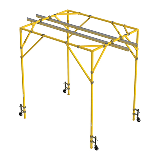
BOXED-FRAME RAIL FALL ARREST SYSTEM: The four and/or six leg Boxed-Frame System is a frame supported
trolley rail assembly for overhead anchorage of Capital Safety fall arrest or fall arrest restraint equipment.
Wheeled trolleys travel along rail assemblies and serve as moving anchorage points for Self-Retracting Lifelines
(SRLs) and Lanyards. The rail assemblies are supported in an overhead position by an overhead super structure.
Swiveling wheel assemblies and top-wind jacks provide portability and secure positioning.
IMPORTANT: The Boxed-Frame Rail Fall Arrest System shall only be used as supporting structure for Personal
Fall Protection Equipment. It shall not be used as supporting structure for lifting equipment.
GLIDE RAIL: The Glide Rail System (Figure 2) is the main component of the frame system. It is a rail and trolley
system for horizontal anchorage of Capital Safety personal fall arrest or fall restraint equipment. Wheeled Trolleys
travel along a Rail Assembly and serve as moving anchorage points for Self Retracting Lifeline (SRLs) or Lanyards. Rail
sections are supported from the overhead structure by Mounting Brackets comprised of various combinations of Beam
Clamps, Connector Channels, and Extensions.
Form: 5903123 Rev: D
CEN/TS 16415:2013
CE Type Test
No. 0086
BSI Product Services
Kitemark Court
Davy Avenue
Knowlhill, Milton Keynes
MK5 8PP, UK
USER INSTRUCTION MANUAL
BOXED-FRAME RAIL FALL ARREST SYSTEM
Figure 1 - FlexiGuard Boxed-Frame Rail Fall Arrest System
NOTE: This fi gure illustrates a Four-Leg Boxed-Frame System.
Boxed-Frame Systems are custom designed to customer
requirements and will vary with the intended application.
CE Production Quality Control
No. 0086
BSI Product Services
Kitemark Court
Davy Avenue
Knowlhill, Milton Keynes
MK5 8PP, UK
Boxed Frame Rail
Fall Arrest System
Model Numbers:
8530245, 8530345, 8530491, 8546050, 8560588
© Copyright 2014, Capital Safety
Advertisement
Table of Contents

Related Manuals for DBI SALA Flexiguard 8530245


Summary of Contents for DBI SALA Flexiguard 8530245
- Page 1 CEN/TS 16415:2013 CE Type Test CE Production Quality Control Boxed Frame Rail Fall Arrest System No. 0086 No. 0086 BSI Product Services BSI Product Services The Ultimate in Fall Protection Kitemark Court Kitemark Court Model Numbers: Davy Avenue Davy Avenue Knowlhill, Milton Keynes Knowlhill, Milton Keynes 8530245, 8530345, 8530491, 8546050, 8560588...
- Page 2 Figure 2 - Glide Evolution Rail System Rail Assembly SRL Trolley Lanyard Trolley (Purchased Seperately) Self Retracting Lifeline (Purchased Seperately) Lanyard (Purchased Seperately) Figure 3 - Typical System Layout Design ≥30° or 6 ft. ≥30° or 6 ft. Length of safe walking area Width of safe working area...
-
Page 3: System Design
SYSTEM DESIGN HEAT: The frame system is not designed for use in high temperature environments (greater than 130° F, 54° C). Protection of the system must be provided if exposure to welding, metal cutting, or similar activities are expected. CORROSION: System components may be damaged by exposure to environments where caustic vapors or chemicals are present. - Page 4 Table 1 - Trolleys Four-Wheeled, Small-Eyed SRL Trolleys Four-Wheeled, Large-Eyed Lanyard Trolleys Connection point for SRLs attached with an approved Double- Connection point for Double-Locking Snap Hooks used on Locking Carabiner. Small eye minimizes loss of overhead various types of Lanyards. Model Numbers and dimensions clearance, keeping the worker’s attachment point as high as are as follows: possible relative to their dorsal D-Ring.
-
Page 5: System Requirements
APPLICATIONS Purpose: Personal Protective Equipment Against Falls From Height The frame system combines easy access to elevated work areas with fall protection from the ground for the duration of the work performed. The system included is a horizontal rail assembly with up to four trolleys that ride in track rails to any position along the rail assembly. - Page 6 CONNECTIONS: Only use self-locking snap hooks and carabiners with this equipment. Only use connectors that are suitable to each application. Ensure all connections are compatible in size, shape, and strength. Do not use equipment that is not compatible. Ensure all connectors are fully closed and locked. Capital Safety connectors (snap hooks and carabiners) are designed to be used only as specifi...
- Page 7 LOWERING AND RAISING A MANUAL ADJUSTABLE FRAME SYSTEM NOTE: This section only applies to Frame Systems that are manually adjusted. If your system is hydraulically adjustable, move to the section titled Positioning and Stabilizing the Frame System. If your system is not adjustable, disregard this section and move to the section titled Positioning and Stabilizing the Frame System.
- Page 8 Step 5: Repeat steps 1 and 4 for the two remaining legs on the other side and install the pins to hold position. Figure 8 - Finished Setting Desired Height Count the exposed holes in the tubes to ensure the same number are showing on all legs.
- Page 9 POSITIONING AND STABILIZING THE FRAME SYSTEM NOTE: Once the unit is raised and all legs are secured with the provided hardware, the unit can be positioned to the required fall-protection area. It is recommended that the unit be moved in the lowered position. IMPORTANT: Be sure to have someone spot the unit while moving the system near overhead power lines, electrical outlets, or any other dangerous overhead objects.
- Page 10 LOWERING AND RAISING A HYDRAULIC ADJUSTABLE FRAME SYSTEM NOTE: This section only applies to Frame Systems that are hydraulically adjusted. If your system is not hydraulically adjustable and has been properly set up, disregard this section and move to the section titled Operation and Use.
- Page 11 Step 4: On the frame system, release the four (4) lock levers so they are in the “Engageg Position”. Step 5: Plug in the power unit’s electrical cord. IMPORTANT: Be sure to have someone spot the frame system while raising the system near overhead power lines, electrical outlets, or any other dangerous overhead objects.
- Page 12 TOWING THE SYSTEM Towing kits are an optional accessory for a box frame system. If your system was not supplied with this accessory please skip to the next section. Towing kits come in two basic styles: tow bar style (Figure 12) and fork pocket style (Figure 13). Tow bar style is intended for pintle or ball style hitches.
-
Page 13: Operation And Use
Figure 13 - Towing Kit Installation and Use - Fork Pocket Style STEP 1: Using a crane or forklift set Step 1: the fork pocket tube assembly into position on the desired side of the system. Secure using the supplied pin and clevis assemblies. - Page 14 Figure 14 - Safe Working Zone Front View Top View Safe Working Zone Safe Working Zone Safe Working Zone NOTE: Do not allow the lifeline to exceed a 30 degree working angle from the anchor point; work outside of a 6 ft working radius from the anchor point, whichever comes fi...
- Page 15 WARNING: Read and follow the manufacturer’s instructions for the personal fall arrest equipment selected for use with the frame system. IMPORTANT: Body belts are not allowed for free fall situations. Body belts increase the risk of injury during fall arrest in comparison to a full body harness. Limited suspension time and the potential for improperly wearing a body belt may result in added danger to the user’s health.
-
Page 16: Specifications
INSPECTION STEPS: Step 1. Inspect the frame system for physical damage. Look carefully for any signs of cracks, dents, or deformities in the metal. Make certain the components are not deformed in any way and that they move correctly. Step 2. Inspect the frame system for signs of excessive corrosions. - Page 17 TERMINOLOGY Authorized Person A person assigned by the employer to perform duties at a location where the person will be exposed to a fall hazard (otherwise referred to as “user” for the purpose of these instructions). Rescuer Person or persons other than the rescue subject acting to perform an assisted rescue by operation of a rescue system.
- Page 18 LABELING The following labels should be securely attached to the frame system and fully legible: (Example only. When ordering replacement label, please specify 7 digit part number in lower left corner.) 9509349 Rev. A READ INSTRUCTIONS: The user/rescuer must read and understand these ELECTROCUTION HAZARD: instructions or have them Watch for Overhead Power...
-
Page 19: Inspection And Maintenance Log
INSPECTION AND MAINTENANCE LOG SERIAL NUMBER: MODEL NUMBER: DATE PURCHASED: DATE OF FIRST USE: INSPECTION DATE INSPECTION ITEMS CORRECTIVE ACTION MAINTENANCE NOTED PERFORMED Approved By: Approved By: Approved By: Approved By: Approved By: Approved By: Approved By: Approved By: Approved By: Approved By: Approved By: Approved By:... -
Page 20: Limited Lifetime Warranty
LIMITED LIFETIME WARRANTY Warranty to End User: D B Industries, Inc., dba CAPITAL SAFETY USA (“CAPITAL SAFETY”) warrants to the original end user (“End User”) that its products are free from defects in materials and workmanship under normal use and service. This warranty extends for the lifetime of the product from the date the product is purchased by the End User, in new and unused condition, from a CAPITAL SAFETY authorized distributor.
Need help?
Do you have a question about the Flexiguard 8530245 and is the answer not in the manual?
Questions and answers