Advertisement
Available languages
Available languages
Quick Links
LANYARDS WITH INTEGRAL ENERGY ABSORBERS AND ENERGY ABSORBER
COMPONENTS USED IN PERSONAL FALL ARREST SYSTEMS (ANSI Z359.1)
This manual is intended to meet the Manufacturer's Instructions as required by ANSI Z359.1 and should be used
as part of an employee training program as required by OSHA.
EZ Stop II
EZ Stop II
Web Lanyards
Shockwave Lanyards
IMPORTANT: Before using this equipment record the product identification information (found on the I.D. label)
in the inspection and maintenance log in section 10.0 of this manual.
DESCRIPTIONS
EZ STOP® II WEB LANYARDS
1-in. (2.5 cm) web, 9503175 hook each end.
1-in. (2.5 cm) web, 9503175 hook one end, 2007153 hook other end.
1-in. (2.5 cm) web, 9503175 hook one end, 1200049 wire pipe clamp other end.
1-in. (2.5 cm) web, 9503175 hook one end, 2000108 carabiner other end.
1-in. (2.5 cm) web, web loop one end, 2007153 hook other end.
1-in. (2.5 cm) web, web loop one end, 9503175 hook other end.
1-in. (2.5 cm) web, adjustable, 9503175 hook each end.
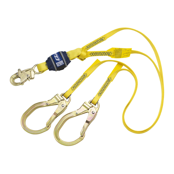
1-in. (2.5 cm) web, 100% tie-off, 9503175 hook center, 2007153 hook leg ends.
1-in. (2.5 cm) web, 100% tie-off, 9503175 hook center and leg ends.
1-in. (2.5 cm) web, 100% tie-off, 9503175 hook center, 2000108 carabiner leg ends.
1-in. (2.5 cm) web, 100% tie-off, web loop center, 2007153 hook leg ends.
1-in. (2.5 cm) web, 100% tie-off, web loop center, 9503175 hook leg ends.
Form: 5902143 Rev: L
Instructions for the following series products:
USER INSTRUCTION MANUAL
Figure 1 - EZ STOP
EZ Stop II
EZ Stop II
Cable Lanyards
Tie-back Lanyards
EZ Stop Lanyards
ShockWave Lanyards
EZ Stop Retrax Lanyards
(See back pages for model numbers)
®
Lanyards
EZ Stop III
EZ Stop III
Web Lanyards
Energy Absorber
Component
© Copyright 2009, DB Industries, Inc.
Shockwave 2
EZ Stop Retrax
Lanyard
Retracting Lanyard
Advertisement

Related Manuals for DBI SALA EZ Stop


Summary of Contents for DBI SALA EZ Stop
- Page 1 COMPONENTS USED IN PERSONAL FALL ARREST SYSTEMS (ANSI Z359.1) This manual is intended to meet the Manufacturer’s Instructions as required by ANSI Z359.1 and should be used as part of an employee training program as required by OSHA. Figure 1 - EZ STOP ® Lanyards...
- Page 2 EZ STOP® II SHOCKWAVE™ WEB LANYARDS 1-in. (2.5 cm) elastic web, 9503175 hook each end. 1-in. (2.5 cm) elastic web, 9503175 hook one end, 2007153 hook other end. 1-in. (2.5 cm) elastic web, web loop one end, 2007153 hook other end.
-
Page 3: Safety Information
SAFETY INFORMATION FORM NO:5908271 Rev. A Please read, understand, and follow all safety information contained in these instructions prior to the use of this Work Positioning/Travel Restraint Lanyard. FAILURE TO DO SO COULD RESULT IN SERIOUS INJURY OR DEATH. These instructions must be provided to the user of this equipment. Retain these instructions for future reference. -
Page 4: System Requirements
APPLICATIONS PURPOSE: DBI-SALA Energy Absorbing Lanyards and Energy Absorbers are intended to be used as part of a personal fall arrest system. Applications for these products include inspection work, construction and demolition, maintenance, oil production, confined space rescue, and similar activities where there exists the possibility of a fall. This equipment is specially designed to dissipate fall energy and limit fall arrest forces transferred to the body. - Page 5 connectors that are suitable to each application. Ensure all connections are compatible in size, shape and strength. Do not use equipment that is not compatible. Ensure all connectors are fully closed and locked. DBI-SALA connectors (snap hooks and carabiners) are designed to be used only as specified in each product’s user instructions.
-
Page 6: Operation And Use
A. 3,000 pounds (13.3kN) for non-certified anchorages, or B. Two times the foreseeable force for certified anchorages. When more than one work positioning system is attached to an anchorage, the strengths set forth in (A) and (B) above shall be multiplied by the number of systems attached to the anchorage. OPERATION AND USE WARNING: Do not alter or intentionally misuse this equipment. - Page 7 6 ft. (1.8 m). Avoid working above your anchorage level to avoid an increased free fall distance. IMPORTANT: Some energy absorbing lanyards, such as EZ Stop® Retrax™ and the Shockwave lanyards, make use of retracting devices designed to shorten their free length. These devices do not decrease free fall distance C.
- Page 8 With one lanyard leg attached, the worker can move to a new location, attach unused lanyard leg, and disconnect attached leg. This procedure is repeated until a new location is reached. With the EZ Stop® Energy Absorber attached to...
- Page 9 Figure 11 - Acceptable Designed Retainers Figure 12 - Acceptable Attachment 5. When leapfrogging from one anchorage point to the next (such as traversing a Figure 13 - Max Lanyard Reach horizontal or vertical structure) do not connect to anchorage points that are further apart than the lanyard length (as marked on the lanyard label).
- Page 10 ATTACHING A LANYARD WITH WEB LOOPS: See Figure 17. Figure 17 - Web Loop Connection 1. Insert the energy absorbing lanyard web loop through the harness web loop or D-ring. Insert lanyard web loop through 2. Insert the opposite end of the energy absorbing lanyard through web loop or D-ring on harness Harness web loop the connecting web loop.
- Page 11 Figure 19 - i-Safe RFID Tag Figure 20 - Inspecting the Energy Abosrber for Activation The following inspection items are indications Torn webbing that the Energy Absorber has been subjected i-Safe to impact loading and has been activated. RFID Tag Torn or broken cover Open end or ripped out stitching...
-
Page 12: Specifications
The maximum arresting force of DBI-SALA Energy Absorbing Lanyards and components when dynamically tested in accordance with ANSI Z359.1 is 900 lbs. (4 kN). (EZ STOP® III and ShockWave 2 models less than 6 ft. [1.8 m] in length, maximum arresting force is 1800 lbs. [8 kN], Shockwave 2 Tie-back, maximum arrresting force is 1350 lbs [6 kN]). - Page 13 TERMINOLOGY Authorized Person: A person assigned by the employer to perform duties at a location where the person will be exposed to a fall hazard (otherwise refered to as “user” for the purpose of these instructions). Rescuer: Person or persons other than the rescue subject acting to perform an assisted rescue by operation of a rescue system.
- Page 14 These labels must be securely attached to the noted CSA approved lanyards and be fully legible. Warning Label - All CSA Approved Lanyards ® ID / Warning Label - CSA Approved EZ Stop II Web Lanyards ® ID Label - CSA Approved EZ Stop...
- Page 15 100% Tie-off Lanyard Warning Label Shockwave 2 Tie Back Lanyards ID Label Front and Back Shockwave 2 Tie Back Lanyards Warning Label Shockwave 2 Tie Back Lanyards Impact Indicator Label All EZ Stop III ANSI Approved Lanyards - I.D. / Warning Label...
-
Page 16: Inspection And Maintenance Log
10.0 INSPECTION AND MAINTENANCE LOG SERIAL NUMBER: MODEL NUMBER: DATE PURCHASED: DATE OF FIRST USE: INSPECTION DATE INSPECTION ITEMS CORRECTIVE ACTION MAINTENANCE NOTED PERFORMED Approved By: Approved By: Approved By: Approved By: Approved By: Approved By: Approved By: Approved By: Approved By: Approved By: Approved By:... - Page 17 Models - ANSI: 1100456 1107951 1220262 1220680 1221115 1224349 1240068 1240277 1240620 1240880 1241465 1244351 1100750 1107952 1220265 1220681 1221116 1224350 1240071 1240278 1240626 1240901 1241480 1244353 1100756 1107958 1220267 1220682 1221117 1224354 1240074 1240279 1240627 1240902 1241481 1244354 1100762 1107959 1220268 1220701...
- Page 18 Models - CSA: CSA Class Model Numbers Max. Arresting Force Max. Elongation Min. Mass of Worker Max. Mass of Worker 900 lbf (4.0 kN) 3.9 ft (1.2 m) 100 lbs (45 kg) 254 lbs (115 kg) 1100320C 1101859C 1106062C 1108530C 1109433C 1220046C 1220296C...
- Page 19 Este manual visa atender às instruções do fabricante conforme a norma ANSI Z359.1 e deve ser usado como parte de um programa de treinamento de funcionários, conforme as exigências da OSHA. Figura 1 - Talabartes EZ STOP ® Talabartes para...
- Page 20 Teia de 3,5 cm (1 3/8 pol.), teia em anel em uma extremidade, gancho 2007153 na outra. Teia de 3,5 cm (1 3/8 pol.), teia em anel em uma extremidade, gancho 9503175 na outra. COMPONENTE DE ABSORÇÃO DE ENERGIA EZ STOP ®...
-
Page 21: Informações De Segurança
INFORMAÇÕES DE SEGURANÇA 5908271 REV. A PT-B Leia, compreenda e siga todas as informações de segurança contidas nestas instruções antes de utilizar este talabarte de posicionamento de trabalho/restrição de deslocamento. O NÃO CUMPRIMENTO DESTAS EXIGÊNCIAS PODERÁ CAUSAR FERIMENTOS GRAVES OU MORTE. Estas instruções deverão ser fornecidas ao usuário deste equipamento. -
Page 22: Requisitos Do Sistema
APLICAÇÕES FINALIDADE: os talabartes de absorção de energia e os absorvedores de energia da DBI-SALA devem ser usados como parte de um sistema individual de prevenção contra quedas. As aplicações para esses produtos incluem trabalhos de inspeção, construção e demolição, manutenção, produção de petróleo, resgate em espaços confinados e atividades semelhantes em que exista a possibilidade de queda. - Page 23 em tamanho, formato e resistência. Não use equipamentos que não sejam compatíveis. Assegure-se de que todos os conectores estejam completamente fechados e travados. Os conectores da DBI-SALA (ganchos de engate e mosquetões) são projetados para serem usados apenas conforme especificado nas instruções de uso de cada produto. Veja a figura 3 para conexões inadequadas. Os ganchos de engate e mosquetões da DBI-SALA não devem ser conectados: A um anel em “D”...
- Page 24 Em um acoplamento malfeito, em que itens protuberantes do gancho de engate ou do mosquetão ficam presos na âncora, e sem confirmação visual parecem estar totalmente acoplados no ponto de ancoragem. Um ao outro. Diretamente a talabartes ou amarras de rede ou corda (exceto se as instruções do fabricante para o talabarte e o conector permitirem essa conexão especificamente).
- Page 25 IMPORTANTE: alguns talabartes de absorção de energia, como o EZ Stop® Retrax™ e os talabartes Shockwave, usam dispositivos de retração projetados para diminuir o comprimento. Esses dispositivos não reduzem a distância da queda livre. FORÇAS DE PREVENÇÃO CONTRA QUEDA: o sistema de prevenção contra queda instalado deve manter as forças de prevenção contra queda abaixo de 8,0 kN (1.800 libras) quando usado com o arnês completo para o corpo.
- Page 26 Esse procedimento é repetido até se chegar a um novo local. Com ao anel em “D” traseiro o talabarte EZ Stop® II Shockwave de envolvimento total, somente uma perna do talabarte deve ser fixada ao ponto de ancoragem ou ao conector de ancoragem quando se chegar a um local de trabalho.
- Page 27 Figura 11 – Retentores projetados aceitáveis Figura 12 – Fixação aceitável 5. Ao saltar de um ponto de ancoragem para o próximo (como, por exemplo, atravessar uma Figura 13 – Alcance máximo do talabarte estrutura horizontal ou vertical), não faça a conexão a pontos de ancoragem que estejam mais distantes do que o comprimento do talabarte (conforme marcado na etiqueta do talabarte).
- Page 28 1. Insira o talabarte de absorção de energia com teia em anel através da teia Figura 17 – Conexão da teia em anel em anel do arnês ou do anel em “D”. 2. Insira a extremidade oposta do talabarte de absorção de energia através da teia em anel para conexão.
- Page 29 Figura 19 - Etiqueta IDRF Figura 20 – Inspeção do absorvedor de energia para ativação i-Safe Os itens de inspeção a seguir são indicações Trama rasgada de que o absorvedor de energia foi submetido a cargas de impacto e ativado. Etiqueta IDRF i-Safe Capa rasgada ou rompida...
- Page 30 A força de proteção máxima dos talabartes e componentes de absorção de energia da DBI-SALA testados dinamicamente de acordo com a ANSI Z359.1 é de 4 kN (900 libras). (Nos modelos EZ STOP® III e ShockWave 2 com comprimento menor que 1,8 m [6 pés], a força de interrupção máxima é de 8 kN [1.800 libras], no talabarte de amarra Shockwave 2, a força de interrupção máxima é...
- Page 31 TERMINOLOGIA Pessoa autorizada: uma pessoa designada pelo empregador para desempenhar funções em um local onde a pessoa estará exposta a riscos de queda (nessas instruções normalmente denominada “usuário”). Equipe de resgate: pessoa, ou pessoas, que não seja a pessoa a ser resgatada, que age para executar um resgate auxiliado utilizando um sistema de resgate.
- Page 32 Estas etiquetas devem ser afixadas firmemente aos talabartes aprovados pela CSA e devem estar totalmente visíveis. Etiqueta de avisos - Todos os talabartes aprovados pela CSA Etiqueta de identificação/avisos - Talabartes para teias EZ Stop II aprovados pela CSA ®...
- Page 33 Visão dianteira e traseira da etiqueta de identificação dos talabartes de amarra Shockwave 2 Etiqueta de avisos dos talabartes de amarra Shockwave 2 Etiqueta do indicador de impacto dos talabartes de amarra Shockwave 2 Todos os talabartes EZ Stop III aprovados pela ANSI - Etiqueta de identificação/avisos...
- Page 34 10.0 REGISTRO DE INSPEÇÕES E MANUTENÇÃO NÚMERO DE SÉRIE: NÚMERO DO MODELO: DATA DE AQUISIÇÃO: DATA DE INÍCIO DO USO: DATA DE INSPEÇÃO: ITENS OBSERVADOS AÇÃO CORRETIVA MANUTENÇÃO NA INSPEÇÃO EXECUTADA Aprovado por: Aprovado por: Aprovado por: Aprovado por: Aprovado por: Aprovado por: Aprovado por: Aprovado por:...
- Page 35 Modelos – ANSI: 1100456 1107951 1220262 1220680 1221115 1224349 1240068 1240277 1240620 1240880 1241465 1244351 1100750 1107952 1220265 1220681 1221116 1224350 1240071 1240278 1240626 1240901 1241480 1244353 1100756 1107958 1220267 1220682 1221117 1224354 1240074 1240279 1240627 1240902 1241481 1244354 1100762 1107959 1220268 1220701...
- Page 36 Models - CSA: Classe CSA Números dos modelos Força máx. Alongamento máximo Peso mínimo Peso máximo de in ter rupção do tra balhador do tra balhador 4,0 kN (900 libras) 1,2 m (3,9 pés) 45 kg (100 libras) 115 kg (254 libras) 1100320C 1101859C 1106062C...
- Page 37 GARANTIA GLOBAL DE PRODUTOS, RECURSO LIMITADO E LIMITAÇÃO DE RESPONSABILIDADES GARANTIA: OS SEGUINTES TERMOS SUBSTITUEM TODAS AS GARANTIAS OU CONDIÇÕES, EXPRESSAS OU IMPLÍCITAS, INCLUINDO AS GARANTIAS OU CONDIÇÕES DE COMERCIALIZAÇÃO OU ADEQUAÇÃO PARA UM FIM ESPECÍFICO. A menos que o contrário seja estipulado por leis locais, os produtos de proteção contra quedas da 3M possuem garantia contra defeitos de fábrica na fabricação e nos materiais por um período de um ano a partir da data da instalação ou do primeiro uso por parte do proprietário original.
- Page 40 U.S. PRODUCT WARRANTY, LIMITED REMEDY AND LIMITATION OF LIABILITY WARRANTY: THE FOLLOWING IS MADE IN LIEU OF ALL WARRANTIES OR CONDITIONS, EXPRESS OR IMPLIED, INCLUDING THE IMPLIED WARRANTIES OR CONDITIONS OF MERCHANTABILITY OR FITNESS FOR A PARTICULAR PURPOSE. Unless otherwise provided by applicable law, 3M fall protection products are warranted against factory defects in workmanship and materials for a period of one year from the date of installation or fi...
Need help?
Do you have a question about the EZ Stop and is the answer not in the manual?
Questions and answers