
Related Manuals for 3M W-2808/37027


Summary of Contents for 3M W-2808/37027
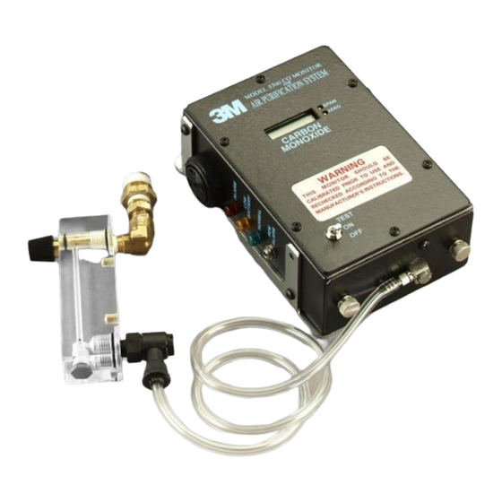
- Page 1 3Carbon Monoxide Monitor and Retrofit Carbon Monoxide Monitor Kit W-2808/37027 User Instructions (Keep these instructions for reference)
-
Page 2: Table Of Contents
– Do Not Use For – General Description SPECIFICATIONS PRODUCTS, ACCESSORIES AND PARTS – 3M Carbon Monoxide Monitor – 3M Retrofit Carbon Monoxide Monitor Kit W-2808/37027 – 3M Accessories and Parts ASSEMBLY SET UP PROCEDURES AND PERFORMANCE CHECK – Monitor Calibration Frequency OPERATING INSTRUCTIONS –... -
Page 3: General Safety Information
W WARNING • These products are designed for carbon monoxide monitoring. Misuse may result in sickness or death. For proper use, see supervisor or User Instructions, or call 3M in U.S.A., 1-800-243-4630. In Canada, call Technical Service at 1-800-267-4414. • The impedance of any connected load device at the REM ALARM (remote alarm) jack must be greater or equal to 12 ohms, when operating from internal batteries or AC adapter. -
Page 4: Use Instructions And Limitations
Retrofit CO Monitor Kit W-2808/37027. 3 / 8 The retrofit kit includes the 3M CO monitor and accessories to attach the CO monitor to a -inch port on a filter and regulator panel that does not currently have CO monitoring capability, such as the 3M Compressed Air Filter and Regulator Panel W-2806/07006. - Page 5 Front Panel On/Off/Test Switch This switch is a three-position type with alternate ON and OFF positions, and a momentary TEST position. Switch is located at the lower left side. Display Display is a centrally located LCD type and is refreshed every 0.8 seconds; the red ALARM light faintly blinks at the same time.
- Page 6 Bottom A rectangular opening in the bottom allows clearance for the sensor that is mounted to the upper face of the bottom plate. The bottom plate is held in place by two knurled thumbscrews. The sample inlet fitting and tubing extends from the outer face of the bottom plate. Right Side These items are aligned toward the rear of the right side panel.
-
Page 7: Specifications
SPECIFICATIONS Sensor – Electrochemical/CO specific Readout – Direct read LCD Range – 0-199 ppm Alarm – 85 dBA at 10 ppm CO (5 ppm Canada) Sensor Life – Approximately 30 months Sensor Replacement – User allowed to replace sensor Intrinsic Safety – Class I, Div I, Group A, B, C, D (when operated on battery power) Power –... -
Page 8: Products, Accessories And Parts
Retrofit Carbon Monoxide Monitor Kit W-2808/37027* The 3M retrofit kit allows the 3M CO monitor to be used with filter and regulator panels that do not currently have CO monitoring capability, such as the 3M compressed air filter and regulator panel W-2806/07006*. -
Page 9: Assembly
If you are installing the flow meter on the 3M compressed air filter and regulator panel W-2806/07006, you will need to remove the plug from the CO sampling port located above the quick disconnect outlets on the panel. - Page 10 Retrofit CO Monitor Kit-includes items 1-11 W-2806/07006 3M Compressed Air Filter and Regulator Panel (Sold Separately) SPAN ZERO CARBON MONOXIDE TEST Fig. 3 Assembled 3M Retrofit Kit W-2808/37027 attached to 3M Compressed Air Filter and Regulator Panel W-2806/07006 (sold separately).
-
Page 11: Set Up Procedures And Performance Check
3. Remove the plastic sample tube from the black tube lock collar on top of the flow meter. Introduce a sample of zero air to the sample tube (see User Instructions for the 3M Calibration Kit 529-04-48 or 529-04-49). The sample flow should be between 0.5 and 1.5 scfh. -
Page 12: Operating Instructions
OPERATING INSTRUCTIONS The following instructions are intended to serve as a guideline for the use of the 3M Carbon Monoxide Monitor. It is not to be considered all-inclusive, nor is it intended to replace the policy and procedures for each facility. -
Page 13: Calibration
Zero Adjustment Remove sample tube from the black tube lock collar on top of the flow meter. Introduce a sample of zero air to the sample tube (see User Instructions for the 3M Calibration Kit 529-04-48 or 529-04-49). The sample flow should be between 0.5 and 1.5 scfh. -
Page 14: Replacement Part Instructions
REPLACEMENT PART INSTRUCTIONS Batteries Check batteries each time instrument is turned on by noting that the green NORMAL light is on and the yellow LOW BATTERY light is off. If the yellow light is on, the batteries need replacing. Two 9 volt alkaline batteries will power the monitor continuously for approximately 30-35 hours. Batteries are contained in drawers on the right-hand side. - Page 15 Wire Color Detector Terminal Black CNTR Circuit board/ sensor to flow Blue block mounting screws. SENSING Be sure flow block cavity and o-ring are dry Wire connectors’ and clean of oils, dirt etc. The o-ring must be circuit board positioned evenly in the bottom of the flow block cavity.
-
Page 16: Troubleshooting
TROUBLESHOOTING Low battery As the battery voltage declines toward the end of its life, the following indications occur: a) At 7.0 volts, the amber LOW BATTERY light will come on. Battery replacement is recommended at this point, but continued operation is still possible. b) At 6.4 volts, the buzzer will beep at intervals of about 7 seconds. - Page 17 Problem Potential Cause Corrective Action With span gas flowing Span potentiometer may be Adjust the zero potentiometer through the monitor after turned clockwise all the way counterclockwise to 199 and approximately one-minute then turn down to value of display reads one (1) to the span gas far left The sensor has lost sensitivity...
-
Page 18: Important Notice
(1) and two (2) year periods respectively. 3M shall not be liable for loss of use of any of its products or incidental or consequential costs, expenses, or damages incurred by the purchaser or any other user. -
Page 19: For More Information
FOR MORE INFORMATION In United States, contact: Internet: www.3M.com/occsafety Technical Assistance: 1-800-243-4630 For other 3M products: 1-800-3M-HELPS or 1-651-737-6501 In Canada, contact: Internet: www.3M.com/CA/occsafety Technical Assistance: 1-800-267-4414 For other 3M products: 1-800-364-3577 3M Occupational Health and Environmental Safety Division 3M Center, Building 235-2W-70 P.O.
Need help?
Do you have a question about the W-2808/37027 and is the answer not in the manual?
Questions and answers