3M M150 User Manual
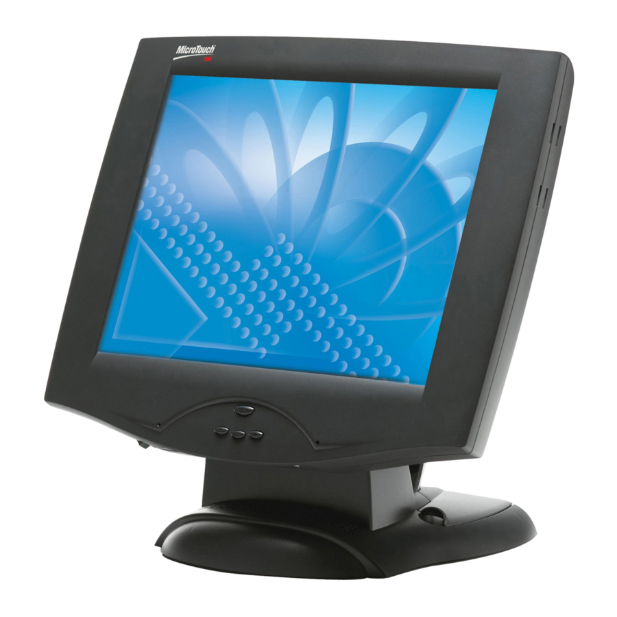
Flat panel display touch monitor
Hide thumbs
Also See for M150:
- User manual (37 pages) ,
- Specifications (2 pages) ,
- Dimensional drawing (1 page)
Table of Contents
Advertisement
Quick Links
Download this manual
See also:
User Manual
Advertisement
Table of Contents
Troubleshooting

Related Manuals for 3M M150


Summary of Contents for 3M M150
- Page 1 M150 Flat Panel Display Touch Monitor User Guide 3M Touch Systems, Inc. Read and understand all safety information contained in this document before using this product. 3M Touch Systems, Inc. Proprietary Information...
- Page 2 3M Touch Systems, Inc. warranty, then 3M Touch Systems, Inc. sole obligation and User’s and Purchaser’s exclusive remedy, will be, at 3M Touch Systems, Inc. option, to repair or replace that Product quantity or software media or to refund its purchase price.
-
Page 3: Table Of Contents
Introduction to Flat Panel Displays Native Video Resolution on a Flat Panel Display ...........10 Options for Using Other Video Resolutions.............10 Chapter 2 Setting Up Your M150 FPD Monitor System Requirements ....................11 Unpacking Your Touch Monitor................12 Arm Mounting Option.....................12 Countertop Base Mounting Option .................13 Access to the Video Controls ..................14... - Page 4 M150 FPD Monitor User Guide Chapter 3 Video Display Options Adjusting the M150 Video Display.................23 Auto Config ......................24 Brightness ......................24 Contrast......................25 Color .........................25 Position ......................25 Image ........................26 Miscellaneous Menu ..................27 Lock Out Feature ....................27 Chapter 4 Maintenance and Troubleshooting Maintaining Your Touch Monitor................29 Touch Screen Care and Cleaning ................29...
-
Page 5: Overview
Overview Welcome to the world of 3M Touch Systems — a world where using a computer is as simple as touching the screen. This guide describes how to set up your M150 Flat Panel Display (FPD) touch monitor. This document assumes you have basic computer skills. You should know how to use the mouse and keyboard, choose commands from menus, open and run application programs, and save files. -
Page 6: Explanation Of Symbols
M150 FPD Monitor User Guide DANGER To avoid the risk of fire and/or explosion which will result in serious injury or death: Do not install or use this product in a hazardous location. WARNING To avoid the risk of fire which could result in serious injury or death: Do not remove the cover or back of the monitor. -
Page 7: Service And Repair Indicators
• The product has been dropped or the case has been damaged. • The product shows a distinct change in performance, indicating a need for service. • The power cable or plug is damaged or frayed. 3M Touch Systems, Inc. Proprietary Information... -
Page 8: 3M Touch Systems Support Services
Technical Support is available Monday through Friday 8 a.m. to 8 p.m. US Eastern Standard Time – 9 a.m. to 5 p.m. throughout Europe. You can contact 3M Touch Systems Technical Support (US only -- Eastern Standard Time) by calling the hot line, sending an email, or sending a fax. - Page 9 The M150 monitor also features a space saving design, high resolution, low radiation, and low power consumption. These qualities make the M150 FPD touch monitor ideal for applications that require superior color, resolution, and clarity.
-
Page 10: Chapter 1 Introduction To Flat Panel Displays
M150 FPD Monitor User Guide Note: The M150 FPD has a power LED as well as four buttons for using the on-screen menu and adjusting the video display. Refer to Chapter 3 for more information on these controls. Native Video Resolution on a Flat Panel Display Flat panel displays, unlike CRTs, are optimized to run at one resolution. -
Page 11: Chapter 2 Setting Up Your M150 Fpd Monitor
Easy access helps ensure a smooth setup of the touch monitor. Note: Before setting up your M150 FPD, refer to the Important Safety Information section at the beginning of this document. -
Page 12: Unpacking Your Touch Monitor
Follow the manufacturer's instructions included with the mounting device to properly attach your monitor. In order to arm-mount the M150 FPD, you will need to remove the monitor face from the stand and yoke. 3M Touch Systems, Inc. Proprietary Information... -
Page 13: Countertop Base Mounting Option
Chapter 2 Setting Up Your M150 FPD Monitor Figure 1 Disassembling the Yoke & Base for Arm Mounting Step 1 -- Unlock the yoke. With the unit laying face down safely and securely on a nonabrasive surface, remove the two screws connecting the top of the yoke. Lift yoke and pull down to disengage tabs to remove. -
Page 14: Access To The Video Controls
Turn the positive locking mechanism adjustment knob 1/4 turn (horizontal to vertical) to loosen. Adjust the M150 FPD by pushing on the top front of the monitor until the screen is at the best viewing angle for you. Then turn the adjustment knob a 1/4 turn back to lock in place. -
Page 15: Installing The Video Card And Video Driver
XGA (1024 x 768) Configuring the Display Settings After you connect your M150 FPD and turn on your computer, you may need to configure one or more of these display settings. The ideal settings for this monitor are as follows: •... -
Page 16: Multimedia Features
Figure 5 Multimedia Cables Optional Card Reader Bracket The M150 FPD monitor is available with an optional card reader bracket (and (2) M3 screws) that supports IDTech and MagTech brand electronic card readers. The black version is part number 5013923 and the beige version is 5103924. The M150 has been designed with slots on either side of the bezel to accommodate this card reader bracket. -
Page 17: Connecting The Touch Monitor
Touch Software drivers prior to connecting the touch screen cable. 4. Plug the AC/DC power supply into the M150 FPD. Be sure to use the power supply included with the monitor. Figure 7 Identifying Your Monitor Connections... - Page 18 5. Connect the power cable to the AC/DC supply. Connect the other end to the appropriate AC outlet. Figure 8 Connecting the M150 Cables to your Computer You should be sure all cable connections are secure -- tighten all cable screws. Shaking and vibration may dislodge cables that are improperly connected.
-
Page 19: Cable Management System
Figure 9 Removing the Cable Management Cover 65-2303 Once you have connected your M150 FPD monitor to your computer, you should take advantage of the cable management system designed into the base of the M150 FPD monitor as shown above. -
Page 20: Testing The M150 Fpd
M150 FPD Monitor User Guide Testing the M150 FPD Note: The M150 FPD has a power status light located on the front of the bezel. After connection, turn on the power switch located at the bottom of the front bezel. -
Page 21: Calibrating The Touch Screen
Chapter 2 Setting Up Your M150 FPD Monitor Calibrating the Touch Screen After you connect your touch monitor and install Touch Software, you must calibrate the touch screen. Calibration serves two purposes: • Sets the active area of the touch screen •... -
Page 23: Chapter 3 Video Display Options
• Display a test image or pattern whenever you adjust the video. Adjusting the M150 Video Display Your M150 FPD monitor has four controls to adjust the video display. • MENU – Shows or hides the menu. • SELECT -- Highlights the current menu option or saves the current setting. Press ► or ◄ to change the value. -
Page 24: Auto Config
M150 FPD Monitor User Guide Auto Config To perform an Auto Config, press the ◄/left arrow key once then press SELECT. The Main Menu item Auto Config is used to adjust the configuration of the phase clock vertical and horizontal position automatically. A confirmation box is displayed to confirm the user selection. -
Page 25: Contrast
By adjusting a single color, you can make the picture look warmer (biased towards red) or cooler (biased towards blue). Adjusting all three levels will make colors appear more or less striking. Position 3M Touch Systems, Inc. Proprietary Information... -
Page 26: Image
M150 FPD Monitor User Guide You can use the Position option to center the image on the display manually. Use the ◄/left and ►/right arrow buttons to scroll through the position menu. • H-Position is used to adjust the horizontal image position manually. -
Page 27: Miscellaneous Menu
1. Press SELECT and then press the ◄/left arrow key. Hold both keys for 10 seconds. DO NOT RELEASE. 2. Then press the ►/right arrow key and hold all three keys together for an additional 10 seconds. 3M Touch Systems, Inc. Proprietary Information... -
Page 29: Chapter 4 Maintenance And Troubleshooting
Typically, an isopropyl alcohol and water solution ratio of 50:50 is the best cleaning agent for your touch screen. You can also use straight isopropyl alcohol. In addition, 3M Screen and Keyboard Cleaner CL680 has been tested and approved for this use. -
Page 30: Monitor Installation Problems
M150 FPD Monitor User Guide • Apply the cleaner with a soft, lint-free cloth. Avoid using gritty cloths. • Always dampen the cloth and then clean the screen. Be sure to spray the cleaning liquid onto the cloth, not the screen, so that drips do not seep inside the display or stain the bezel. -
Page 31: Troubleshooting The Touch Screen
Power Management The M150 monitor conforms to the Video Electronics Standards Association (VESA) Display Power Management Signaling (DPMS) standard. To benefit from power management, the monitor must be used in conjunction with a computer and video card that implements the VESA DPMS standard. -
Page 32: Fcc Warning
3M Touch Systems is not responsible for any radio or television interference caused by using other than recommended cables and connectors or by unauthorized changes or modifications to this equipment. - Page 33 Rear Edge of M150 Base Plate Mounting Template Cut Line Base Not Shown (Drawn actual size) 3M Touch Systems Proprietary Information Place this template on mounting surface and drill three holes as shown for mounting screws. The screw heads must be smaller than 0.39" (10 mm) and larger than 0.21" (5.5 mm).
Need help?
Do you have a question about the M150 and is the answer not in the manual?
Questions and answers