Sign In
Upload
Download
Table of Contents
Contents
Add to my manuals
Delete from my manuals
Share
URL of this page:
HTML Link:
Bookmark this page
Add
Manual will be automatically added to "My Manuals"
Print this page
×
Bookmark added
×
Added to my manuals
Manuals
Brands
DriSteem Manuals
Humidifier
250
Installation, operation and maintenance manual
DriSteem 250 Installation, Operation And Maintenance Manual
High-pressure system with water treatment system
Hide thumbs
1
2
3
Table Of Contents
4
5
6
7
8
9
10
11
12
13
14
15
16
17
18
19
20
21
22
23
24
25
26
27
28
29
30
31
32
33
34
35
36
37
38
39
40
41
42
43
44
45
46
47
48
49
50
51
52
53
54
55
56
57
58
59
60
61
62
63
64
65
66
67
68
69
70
71
72
73
74
75
76
77
78
79
80
81
82
83
84
85
86
87
88
89
90
91
92
93
94
95
96
97
98
99
100
101
102
103
104
105
106
107
108
page
of
108
Go
/
108
Contents
Table of Contents
Troubleshooting
Bookmarks
Table of Contents
Warnings and Cautions
Table of Contents
Overview
System Dimensions
Water Quality and Component Overview
System Overview
Components Overview
Dechlorinator Specifications
Single Water Softener Specifications
Duplex Water Softener Specifications
Optional Pretreatment Skid Mounting
Skidded Single Water Softener and Dechlorinator Specifications
Skidded Duplex Water Softener and Dechlorinator Specifications
Skidded Duplex Water Softener Specifications
Reverse Osmosis Specifications
System Operation Temperature
Installation
Components and Tools Needed
Placing Components
Loading the Carbon Media
Loading the Water Softener Media
Piping and Instrumentation Arrangement
Site Requirements
Plumbing and Wiring for Dual Softener 21, 24, 30 Inch Models
Interconnecting Tubing Requirements
Pre-Treatment System Piping
RO System Piping
High-Pressure System Piping
Electrical Installation
Connecting Communication Components
Start-Up Checklist
Pre-Treatment
400 Water Treatment System
High-Pressure System
Operation
System Startup
Softener and Dechlorinator
400 Water Treatment System
High-Pressure System
Softener and RO Checklist
High-Pressure Atomizing System Checklist
Vapor-Logic Keypad/Display
RO Water Treatment System
High-Pressure System
Maintenance
Water Treatment System Components
High-Pressure System Components
Water Treatment Maintenance Information
Water Quality Test Strips
Inlet Water Quality Test Log
RO System Operating Log
High-Pressure System Operating Log
Troubleshooting
Pre-Treatment System Troubleshooting
RO Water Treatment System Troubleshooting
High-Pressure System Troubleshooting
Replacement Parts
Water Treatment System
RO System
RO System Subpanel
High-Pressure System
High-Pressure Dispersion System
Warranty
Advertisement
Quick Links
1
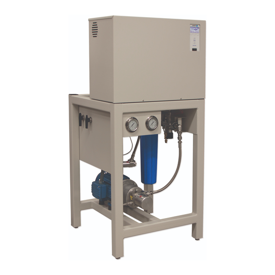
Components Overview
Download this manual
READ AND SAVE THESE INSTRUCTIONS
EVAPORATIVE COOLING
AND HUMIDIFICATION
Hi gh-Pr es su r e Sy st em
w it h Wat er Tr eat me nt S ys te m
Installation, Operation,
and Maintenance Manual
Table of
Contents
Previous
Page
Next
Page
1
2
3
4
5
Advertisement
Table of Contents
Troubleshooting
TROUBLESHOOTING
90
RO water treatment system troubleshooting
94
High-pressure system troubleshooting
96
Need help?
Do you have a question about the 250 and is the answer not in the manual?
Ask a question
Questions and answers
Related Manuals for DriSteem 250
Humidifier DriSteem HUMIDI-TECH Installation, Operation And Maintenance Manual
Humidi-tech and humidi-tech di electric steam humidifiers (32 pages)
Humidifier DriSteem R-1 Series Installation, Operation And Maintenance Manual
(76 pages)
Humidifier DriSteem VT 2 kW Installation, Operation & Maintenance Manual
Vt series electric humidifier (40 pages)
Humidifier DriSteem GTS Users/Installation Instructions And Maintenance Operations Manual
Gas-to-steam humidifiers (36 pages)
Humidifier DriSteem VAPORMIST Installation, Operation And Maintenance Manual
Electric steam humidifiers (20 pages)
Humidifier DriSteem VAPORSTREAM VLC Series Installation, Operation And Maintenance Manual
Electric humidifier (65 pages)
Humidifier DriSteem Vapor-logic 3 Field Conversion Instructions
(4 pages)
Humidifier DriSteem GTS LX Series Installation, Operation And Maintenance Manual
Gas-to-steam humidifier (88 pages)
Humidifier Dristeem XT Installation, Operation And Maintenance Manual
Electrode steam humidifier (64 pages)
Humidifier DriSteem Vaporstream Installation, Operation And Maintenance Manual
Electric humidifier (76 pages)
Humidifier DriSteem XT Series Installation, Operation And Maintenance Manual
Electrode steam humidifiers (68 pages)
Humidifier DriSteem STS SERIES Installation, Operation And Maintenance Manual
Steam-to-steam humidifier (64 pages)
Humidifier DriSteem GTS Series Installation, Operation And Maintenance Manual
Gas-to-steam humidifier (81 pages)
Humidifier DriSteem STS Installation, Operation And Maintenance Manual
Steam-to-steam humidifier (72 pages)
Humidifier DriSteem RTS SDU-I-RX Installation, Operation And Maintenance Manual
(12 pages)
This manual is also suitable for:
500
1000
3500
2500
1750
5500
Table of Contents
Print
Rename the bookmark
Delete bookmark?
Delete from my manuals?
Login
Sign In
OR
Sign in with Facebook
Sign in with Google
Upload manual
Upload from disk
Upload from URL


Need help?
Do you have a question about the 250 and is the answer not in the manual?
Questions and answers