Table of Contents
Advertisement
Quick Links
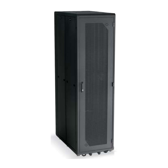
Elite II Server Cabinet
CUSTOMER
Order toll-free in the U.S.: Call 877-877-BBOX (outside U.S. call 724-746-5500)
FREE technical support 24 hours a day, 7 days a week: Call 724-746-5500 or fax 724-746-0746
SUPPORT
Mailing address: Black Box Corporation, 1000 Park Drive, Lawrence, PA 15055-1018
INFORMATION
Web site: www.blackbox.com • E-mail: info@blackbox.com
AUGUST 2004
RM4000
RM4208
RM4100A
RM4209
RM4200A
RM4210
RM4205
RM4211
RM4206
RM411
RM4207
Advertisement
Table of Contents

Related Manuals for Black Box Elite II Series


Summary of Contents for Black Box Elite II Series
- Page 1 Order toll-free in the U.S.: Call 877-877-BBOX (outside U.S. call 724-746-5500) FREE technical support 24 hours a day, 7 days a week: Call 724-746-5500 or fax 724-746-0746 SUPPORT Mailing address: Black Box Corporation, 1000 Park Drive, Lawrence, PA 15055-1018 INFORMATION Web site: www.blackbox.com • E-mail: info@blackbox.com...
- Page 2 TRADEMARKS USED IN THIS MANUAL TRADEMARKS USED IN THIS MANUAL Compaq is a registered trademark of Compaq Computer Corporation. HP is a registered trademark of Hewlett-Packard. Sun is a registered trademark of Sun Microsystems. Any other trademarks mentioned in this manual are acknowledged to be the property of the trademark owners.
-
Page 3: Table Of Contents
A.1 Calling Black Box ........ -
Page 4: Specifications
CHAPTER 1: Specifications 1. Specifications Material: Frame: 14 AWG steel; Side/doors: 18 AWG steel; Corner posts: 14 AWG steel; Mounting rails: 12 AWG steel Rack Spaces: 44U Weight Capacity: 1800 lb. (816.5 kg) on casters Maximum Rail Spacing: Front to rear, 36" (91.4 cm) Anchoring Holes: ⁄... -
Page 5: Introduction
ELITE II SERVER CABINET 2. Introduction 2.1 Overview Mount a variety of multi-vendor servers in the same rack with the Elite II Server Cabinet. It includes three pairs of adjustable M6 rails that can accept “server-specific” side mounting adapters for HP ®... -
Page 6: The Elite Ii Server Cabinet Illustrated
CHAPTER 2: Introduction 2.3 The Elite II Server Cabinet Illustrated RM4200A 28.75" (73 cm) 29" (73.7 cm) 82" (208.3 cm) 84" (213.4 cm) 40" (101.6 cm) 42" (106.7 cm) 24.5" (62.2 cm) 78" (198.1 cm) RM4100A 23.75" (60.3 cm) 24" (61 cm) 82"... -
Page 7: Installation
ELITE II SERVER CABINET 3. Installation 3.1 Elite II Server Cabinet (RM4100A or RM4200A) The Elite II Server Cabinet arrives fully assembled. (See the illustration on the previous page.) 3.2 EIA Rail Adjustment To adjust the rail location: 1. Loosen one of the ⁄... -
Page 8: Vertical Cable Management (Rm4205)
CHAPTER 3: Installation 3.3 Vertical Cable Management (RM4205) The Elite II Server Cabinet Vertical Cable Management (RM4205) can be mounted in each of the enclosure’s four corners. It does not interfere with other equipment or options such as vertical power strips or EIA rail mounting. -
Page 9: Waterfall Cable Management (Rm4206)
ELITE II SERVER CABINET 3.4 Waterfall Cable Management (RM4206) The Waterfall Cable Management (RM4206) manages cables from side to side across the enclosure’s inside top. The unit can be mounted inside the enclosure’s top front and top rear. NSTALLATION NSTRUCTIONS 1. - Page 10 CHAPTER 3: Installation 3. Fasten the Waterfall Cable Management with two #10-32 hex nuts. Use a ⁄ " wrench or nut driver to tighten them. See Figure 3-5. Waterfall Cable Management (RM4206) #10-32 hex nuts with captive lockwashers; use a ⁄...
-
Page 11: Horizontal Cable Management (Rm4207)
ELITE II SERVER CABINET 3.5 Horizontal Cable Management (RM4207) Mounting the Horizontal Cable Management (RM4207) as shown maximizes the number of cable bundles that can be routed from front to rear. This only works with the RM4200A. 5th and 6th holes from top of corner post Highest notch in corner post... -
Page 12: Heavy-Duty Sliding Adjustable Shelf (Rm411) And Other Optional Accessories
CHAPTER 3: Installation 3.6 Heavy-Duty Sliding Adjustable Shelf (RM411) and Other Optional Accessories The Heavy-Duty Sliding Adjustable Shelf (RM411) shelf is 22" (55.9 cm) deep and holds 110 lb.(49.9 kg). Also available are Fixed, Vented Server Shelves (RM399, RM403, and RM410), a Sliding Server Shelf with Fins (RM400), and a 19"... - Page 13 ELITE II SERVER CABINET Figures 3-11 through 3-13 illustrate the mounting brackets installed in three different locations on the rail. You can use any of the brackets illustrated in Figures 3-7 through 3-9 for mounting options 1 through 3 (shown in Figures 3-11 through 3-13).
- Page 14 CHAPTER 3: Installation Exploded view Assembled view Assembled view Exploded view Figure 3-12. Mounting option #2. Assembled view Exploded view Exploded view Assembled view Figure 3-13. Mounting option #3.
-
Page 15: Anti-Tip Leg Assembly
ELITE II SERVER CABINET 3.8 Anti-Tip Leg Assembly Anti-tip legs reduce the cabinet’s chance of tipping over because of equipment extending beyond the enclosure’s front. Use the anti-tip assembly when the enclosure is mounted on leveling glides or casters. When neither glides or casters are used, the enclosure must be securely anchored to the floor. - Page 16 CHAPTER 3: Installation Figure 3-15. Fully extended leg assembly. NOTE If you encounter any technical issues, contact Black Box Technical Support at 724-746-5500 for assistance.
-
Page 17: Top Fan Panel (Rm4000 Or Rm4211)
CHAPTER 3: Installation 4. Verify that each leg travels freely from its fully retracted to fully extended position as it did in step 1 (page 14). If each leg does not travel properly, then call for technical support as described in the Appendix. NOTES The glides in the anti-tip legs may need to be adjusted to be able to extend/retract the legs to accommodate floor conditions. -
Page 18: Appendix. Troubleshooting
• Package it carefully. We recommend that you use the original container. • If you are shipping the Elite II Server Cabinet for repair, make sure you include everything that came in the original package. Before you ship, contact Black Box to get a Return Authorization (RA) number. - Page 19 ELITE II SERVER CABINET 2. With the enclosure on glides or casters, place both leg assemblies under the enclosure’s front. The glide in the anti-tip leg must be at the assembly’s front end (see Figure 3-16). 3. Align the four threaded holes in the stationary channel with the four holes in the enclosure’s bottom (see Figures 3-14 and 3-16).
- Page 20 © Copyright 2004. Black Box Corporation. All rights reserved. 1000 Park Drive • Lawrence, PA 15055-1018 • 724-746-5500 • Fax 724-746-0746...
Need help?
Do you have a question about the Elite II Series and is the answer not in the manual?
Questions and answers