
Related Manuals for JUMO dTRANS T02 Ex


Summary of Contents for JUMO dTRANS T02 Ex
- Page 1 T02 Ex Programmierbarer Messumformer Programmable transmitter B 95.6525.0 Betriebsanleitung Operating Instructions 10.02/00396221...
- Page 2 Besonderheiten / Bedienübersicht II (1) G D [EEx ia] IIC Die Konformitätserklärung (Seite 24) ist zu beachten Innerhalb der EU-Mitgliedsstaaten kann diese Betriebsan- leitung auf Wunsch in einer anderen EU-Landessprache an- gefordert werden.
- Page 3 1 Zielgruppe / Normenkonformität Zielgruppe Der Messumformer JUMO dTRANS T02 Ex Typ 956525/... dient zur Signalumwandlung von Widerstandsthermometern, Thermoele- menten, Widerstands-, Spannungs- und Stromgebern in die Ein- heitssignale 0 … 20mA, 4 … 20mA bzw. 0 … 10V. Eingang, Ausgang und weitere Konfigurationsparameter sind über eine Schnittstelle mittels PC-Programm frei einstellbar.
- Page 4 2 Sicherheitshinweise - Die Errichtung und der Betrieb des Messumformers muss unter Berücksichtigung dieser Betriebsanleitung und den für sie gülti- gen Regeln und Normen erfolgen. - Der Messumformer ist zur Montage auf Tragschiene außerhalb des explosionsgefährdeten Bereiches vorgesehen. Versorgung und Ausgang des Messumformers müssen in der nicht eigensicheren Zone liegen.
- Page 5 2 Sicherheitshinweise Auszug aus der EG-Baumusterprüfbescheinigung PTB 01 ATEX 2149 Messumformer 956525 II (1) G D [EEx ia] IIC Versorgungsstromkreis AC 230V ±10%, 48…63Hz oder (Höchstwerte an den Klemmen AC/DC 20 … 53V, 48…63Hz L1(L+) und N(L-) und PE) Sicherheitstechnische Maximal- spannung U = 253V Ausgangsstromkreis...
-
Page 6: Serienmäßiges Zubehör
3 Typenerklärung / -schilder JUMO dTRANS T02 Ex (1) Grundausführung dTRANS T02 Ex 956525 programmierbarer Messumformer mit Ex-Schutz II (1) G D [EEx ia] IIC (2) Eingang (programmierbar) Werkseitig eingestellt (Pt100 DIN vl / 0 … 100°C) Konfiguration nach Kundenangaben (3) Ausgang (eingeprägter Gleichstrom - programmierbar) - Page 7 3 Typenerklärung / -schilder Die nachfolgende abgebildeten Typenschilder befinden sich auf dem Gehäuse des Messumformers. » » Der F-Nr. (Fabrikations-Nummer) kann das Produktionsdatum (Jahr/ Woche) entnommen werden. Es handelt sich hierbei um die Zeichen 12, 13, 14, 15. Beispiel: F-Nr. 0041367101001360014 Der Messumformer wurde demnach in der 36.
-
Page 8: Technische Daten
4 Technische Daten - Kennzeichnung: II (1) G D [EEx ia] IIC - EG-Baumusterprüfbescheinigung: PTB 01 ATEX 2149 siehe Kapitel 2 „Sicherheitshinweise“ - Konformitätserklärung: siehe Seite 24. - Typenblatt: T 95.6520... -
Page 9: Installation
Für das Errichten/Betreiben sind die Vorschriften gemäß ElexV und diese Betriebsanleitung maßgebend. Die höchstzulässige Umge- bungstemperatur für den Messumformer von +60°C ist unbedingt einzuhalten. Abmessungen 1 2 3 4 5 6 7 8 dTRANS T02 Ex Power Status Span Zero 9 10 11 12 L1 N 15 PE (L + ) (L-) Weitere Installationshinweise entnehmen Sie bitte Kapitel 2 „Sicher-... - Page 10 5 Installation Anschlussplan 1 2 3 4 5 6 7 8 dTRANS T02 Ex Power Status Span Zero 9 10 11 12 L1 N 15 PE (L + ) (L-) Anschluss für Spannungsversorgung lt. Typenschild Analoge Eingänge (Ex) Thermoelement Widerstandsthermometer...
- Page 11 5 Installation Potentiometer in Zweileiterschaltung ≤ 15Ω (R = Leitungswiderstand je Leiter) R =R Potentiometer in Dreileiterschaltung Potentiometer in Vierleiterschaltung Widerstandsferngeber in Dreileiterschaltung Spannungseingang < 1V Spannungseingang ≥ 1V Stromeingang Analoge Ausgänge Spannungsausgang Stromausgang Strom- und Spannungsausgang sind nicht gegeneinander galvanisch ge- trennt.
- Page 12 5 Installation Setup-Schnittstelle Die Setup-Schnittstelle und der ana- loge Ausgang sind nicht galvanisch getrennt. Siehe “Setup-Schnittstelle” auf Seite 12. Anschlussbeispiel Ex-Bereich Nicht Ex-Bereich Regler Anzeige- Registrier- gerät gerät Messumformer 4...20 mA / 0...20 mA 0...10 V...
- Page 13 5 Installation Installationshinweise Sowohl bei der Wahl des Leitungsmaterials bei der Installation als auch beim elektrischen Anschluss des Gerätes sind die Vor- schriften der VDE 0100 „Bestimmungen über das Errichten von Starkstromanlagen mit Nennspannungen unter 1000V“ bzw. die jeweiligen Landesvorschriften zu beachten. Der elektrische Anschluss, sowie Arbeiten im Geräteinneren dürfen ausschließlich von Fachpersonal durchgeführt werden.
- Page 14 5 Installation Der Messumformer ist zur Montage auf Tragschienen außerhalb des explosionsgefährdeten Bereiches vorgesehen. Ein vom Anschlussplan abweichender elektrischer Anschluss kann zur Zerstörung des Gerätes führen. Bei störungsbelasteten Netzen (z. B. Thyristorsteuerungen) soll- te das Gerät über einen Trenntransformator gespeist werden. Netzschwankungen sind nur im Rahmen der angegebenen To- leranzen zulässig (siehe Typenblatt).
- Page 15 6 Instandhaltung Die für die Wartung/Instandsetzung/Prüfung geltenden Bestimmun- gen sind einzuhalten. Im Rahmen der Wartung sind vor allem Teile zu prüfen, von denen die Zündschutzart abhängt. Eine Konfiguration des Messumformers über den Setup-Kreis darf niemals im explosionsgefährdeten Bereich erfolgen. Außerhalb des explosionsgefährdeten Bereiches darf der Anschluss aus sicher- heitstechnischen Gründen (Schutz der ex-relevanten Bauelemente) nur zur kurzzeitigen Konfiguration erfolgen.
-
Page 16: Anzeige- Und Bedienelemente
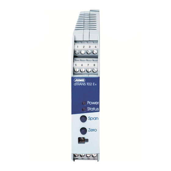
7 Anzeige- und Bedienelemente 1 2 3 4 5 6 7 8 dTRANS T02 Ex Power LEDs für Betriebszustand Status Span Tasten zur Bedienung Zero der Parameterebene Schnittstelle für PC-Setup-Programm 9 10 11 12 L1 N 15 PE (L + ) (L-) - Page 17 7 Anzeige- und Bedienelemente Betriebszustand in der Leucht-/Blinkverhalten Parameterebene (Programmier-Modus) Grenzwert von Limitkomparator 1 Grenzwert von Limitkomparator 2 Feinabgleich (Nullpunkt) Feinabgleich (Endwert) Teach In (0-%-Wert) Unterscheidung der Betriebszustände - Im Betriebszustand Bedienerebene ist die Power-LED permanent an. - Im Betriebszustand Parameterebene blinkt die Power-LED (zu gleichen Teilen an und aus).
-
Page 18: Funktionen Und Bedienung
8 Funktionen und Bedienung Mit Hilfe der Tasten „Span“ und „Zero“ in Verbindung mit den in Ka- pitel 7 „Anzeige- und Bedienelemente“ bereits beschriebenen Blink- zyklen der beiden LEDs „Power“ und „Status“ können Sie den Messumformer bedienen. Bei der Bedienung unterscheiden sich zwei Betriebszustände: - Bedienerebene (Normalbetrieb) - Parameterebene (Programmier-Modus) Bedienerebene... - Page 19 8 Funktionen und Bedienung Werte erhöhen Beim Programmieren der Parameter „Grenzwert 1 und 2“ sowie „Feinabgleich“ (Nullpunkt und Endwert) dient die Taste „Span“ zum Erhöhen eines Wertes (+). Werte verringern Beim Programmieren der Parameter „Grenzwert 1 und 2“ sowie „Feinabgleich“ (Nullpunkt und Endwert) dient die Taste „Zero“ zum Verringern eines Wertes (-).
- Page 20 8 Funktionen und Bedienung Grenzwerte (Limitkomparatoren) einstellen Sie können die beiden Grenzwerte mit Hilfe der Tasten „Span“ und „Zero“ verändern. Der aktuelle Wert wird über den Ausgang ausge- geben. Übernommen wird der Wert durch gleichzeitiges Betätigen der Tasten „Span“ und „Zero“. Die Einstellung der Grenzwerte über die Tasten „Span“...
- Page 21 8 Funktionen und Bedienung Die Grenzwerte (Limitkomparatoren) werden nur über die Status- und die Power-LED angezeigt. Die Open-Collector-Ausgänge sind - im Gegensatz zu den Messumformern 956521/... (PCP) und 956522/... (LCD) - beim Typ 956525/... (Ex) nicht vorhanden. Feinabgleich (Nullpunkt und Endwert) Mit Hilfe des Feinabgleiches können Sie den Nullpunkt und die Steilheit des Ausgangssignales anpassen.
- Page 22 8 Funktionen und Bedienung Teach In Der Parameter „Teach In“ dient dazu, den 0-%-Wert festzulegen. Am Ausgang wird während der Programmierung der Nullwert aus- gegeben (z.B. 4mA). Durch Betätigen der Taste „Zero“ (nur Zero, nicht zusammen mit Span) wird der Wert übernommen. Nach ei- nem Timeout ohne Übernahme steht der alte Wert wieder zur Verfü- gung.
- Page 23 9 Hinweise ..zur Bedienung innerhalb der Parameterebene Das gleichzeitige Betätigen der Tasten „Span“ und „Zero“ als Bestätigung einer Werteingabe setzt voraus, dass vorher mindestens einmal eine der beiden Tasten alleine betätigt wurde. Ist dies nicht der Fall, wird die Betätigung als Aufruf des nächsten Parameters angesehen.
- Page 24 9 Hinweise ..allgemeiner Art Kann kein Parameter verändert werden, haben Sie vielleicht mit Hilfe des Setup-Programmes die Bedienung am Gerät verriegelt. Prüfen Sie die Einstellung durch das Setup-Pro- gramm. Nur, wenn für die entsprechende Ebene keine Verriegelung besteht, können die Einstellungen am Gerät geändert wer- den.
- Page 25 10 PC-Setup-Programm Mit der Bedienung am Messumformer lassen sich nur einige wenige Parameter ändern. Mit dem als Typenzusatz erhältlichen PC-Setup- Programm lassen sich alle Parameter des Messumformers bequem ändern. Über die Setup-Schnittstelle werden der Messumformer und der PC über das „PC-Interface mit TTL/RS232-Umsetzer und Adapter“...
- Page 26 11 Konformitätserklärung...
- Page 28 M. K. JUCHHEIM GmbH & Co Hausadresse: Moltkestraße 13 - 31 36039 Fulda, Germany Lieferadresse: Mackenrodtstraße 14 36039 Fulda, Germany Postadresse: 36035 Fulda, Germany Telefon: 0661 6003-725 Telefax: 0661 6003-681 E-Mail: mail@jumo.net Internet: www.jumo.net...
- Page 29 T02 Ex Programmable transmitter B 95.6525.0 Operating Instructions...
- Page 30 Special features / Overview of operation II (1) G D [EEx ia] IIC Please take note of the Declaration of Conformity (page 24). Within the European Union, these Operating Instructions can be supplied in a different EU language, if requested.
- Page 31 1 Intended use / Conformity with standards Intended use The JUMO dTRANS T02 Ex type 956525/... transmitter is used for converting signals from resistance thermometers, thermocouples, resistance, voltage and current sources into standard 0 — 20mA, 4 — 20mA or 0 — 10V signals.
-
Page 32: Safety Notes
2 Safety notes - The transmitter must be set up and operated in accordance with these operating instructions and the regulations and standards relating to it. - The transmitter is intended for rail mounting outside the hazardous area. Supply and output of the transmitter must be located in the non- intrinsically safe zone. - Page 33 2 Safety notes Extract from the EC Type Examination Certificate PTB 01 ATEX 2149 Transmitter 956525 II (1) G D [EEx ia] IIC Supply circuit 230V AC ±10%, 48 — 63Hz or (maximum values at the 20 — 53V AC/DC, 48 — 63Hz terminals L1(L+) and N(L-) max.
-
Page 34: Type Designation / Labels
3 Type designation / labels JUMO dTRANS T02 Ex (1) Basic version dTRANS T02 Ex 956525 programmable transmitter with Ex protection II (1) G D [EEx ia] IIC (2) Input (programmable) factory-set (Pt100 DIN 4-wire / 0 — 100°C) configuration to customer specification (3) Output (proportional DC current - programmable) factory-set (4 —... - Page 35 3 Type designation / labels The labels shown below are attached to the transmitter housing. » » or specification of range and sensor details on sales no. and serial number as per order factory-set (0 — 20 mA) configuration to customer specification (4 —...
-
Page 36: Technical Data
4 Technical data - Marking: II (1) G D [EEx ia] IIC - EC Type Examination Certificate: PTB 01 ATEX 2149 see Chapter 2 “Safety notes” - Declaration of Conformity: see page 24. - Data Sheet T 95.6520... -
Page 37: Installation
The regulations according to ElexV and these operating instructions apply when setting up and operating the transmitter. It is essential to observe the maximum permissible ambient temperature +60°C. Dimensions 1 2 3 4 5 6 7 8 dTRANS T02 Ex Power Status Span Zero 9 10 11 12... -
Page 38: Connection Diagram
5 Installation Connection diagram 1 2 3 4 5 6 7 8 dTRANS T02 Ex Power Status Span Zero 9 10 11 12 L1 N 15 PE (L + ) (L-) Connection for Supply as on nameplate Analog inputs (Ex) - Page 39 5 Installation Potentiometer in 2-wire circuit ≤ 15Ω (R = lead resistance per R =R conductor) Potentiometer in 3-wire circuit Potentiometer in 4-wire circuit Resistance transmitter in 3-wire circuit Voltage input < 1V Voltage input ≥ 1V Current input Analog outputs Voltage output Current output Current and voltage outputs are not...
- Page 40 5 Installation Setup interface The setup interface and the analog output are not electrically isolated. see “Setup interface” on page 12. Connection example...
- Page 41 5 Installation Installation notes The choice of cable, the installation and the electrical connection must conform to the requirements of VDE 0100 “Regulations on the Installation of Power Circuits with Nominal Voltages below 1000 V” or the appropriate local regulations. The electrical connection, as well as work inside the unit, must only be carried out by qualified personnel.
- Page 42 5 Installation Any electrical connection other than that specified in the connection diagram may result in the destruction of the instrument. With supply networks that are subject to interference (e.g. thyristor control units), the transmitter should be fed from an isolating transformer.
-
Page 43: Maintenance
6 Maintenance The appropriate regulations concerning maintenance, repair and testing must be observed. In particular, all parts on which explosion protection depends must be checked during maintenance. The transmitter must never be configured inside the hazardous area via the setup circuit. For safety reasons (protection of Ex-relevant components), the connection outside the hazardous area may only be made for the purpose of brief configuration. -
Page 44: Displays And Controls
7 Displays and controls 1 2 3 4 5 6 7 8 dTRANS T02 Ex Power LEDs for operational status Status Span Buttons for operating Zero the parameter level Interface for PC setup program 9 10 11 12 L1 N 15 PE... - Page 45 7 Displays and controls Operational status at the Illumination/blink behavior parameter level (programming mode) Limit for limit comparator 1 Limit for limit comparator 2 Fine calibration (zero) Fine calibration (full scale) Teach-in (0 % value) Differentiation of the operational states - In the Operating level status, the power LED is on permanently.
-
Page 46: Functions And Operation
8 Functions and operation You can operate the transmitter by using the “Span” and “Zero” buttons, in conjunction with the blink cycles of the “Power” and “Status” LEDs already described in Chapter 7 “Displays and controls”. In use, two operational states can be distinguished: - Operating level (normal operation) - Parameter level (programming mode) Operating level... - Page 47 8 Functions and operation Increasing values The “Span” button is used to increase a value (+) when programming the parameters “Limit 1 and 2” and “Fine calibration” (zero and full scale). Decreasing values The “Zero” button is used to decrease a value (-) when programming the parameters “Limit 1 and 2”...
- Page 48 8 Functions and operation Setting the limits (limit comparators) You can alter both limits by using the “Span” and “Zero” buttons. The momentary value is produced via the output. The value is accepted by simultaneously pressing “Span” and “Zero”. “Span” and “Zero” can always be used to set the limits. However, the limit query can only be activated through the PC setup program, which is available as an extra.
- Page 49 8 Functions and operation The limits (limit comparators) are indicated only via the status and power LEDs. Unlike the transmitters 956521/... (PCP) and 956522/... (LCD), the open-collector outputs are not available on type 956525/... (Ex). Fine calibration (zero and full scale) Fine calibration can be used to adjust the zero and slope of the output signal.
- Page 50 8 Functions and operation Teach-in The “Teach-in” parameter serves to define the 0 % value. During programming the zero point is produced at the output (e.g. 4mA). This value is accepted by pressing the “Zero” button (“Zero” only, not together with “Span”). After a time-out without acceptance, the old value will be available again.
- Page 51 9 Tips ..on operation within the parameter level A value can only be confirmed by simultaneously pressing the “Span” and ”Zero” buttons when at least one of the buttons has previously been pressed by itself. If this is not the case, the confirmation will be interpreted as a call for the next parameter.
- Page 52 9 Tips ..of a more general nature If none of the parameters can be altered, then you may have locked the operation on the instrument through the setup program. Please check the setting via the setup program. The instrument settings can only be changed when “Operating level”...
-
Page 53: Pc Setup Program
10 PC setup program Operation on the transmitter permits the alteration of only a few parameters. Using the PC setup program, which is available as an extra, all transmitter parameters can easily be altered. The transmitter and the PC are linked with one another through the “PC interface with TTL/RS232 converter and adapter”, via the setup interface. -
Page 54: Declaration Of Conformity
11 Declaration of Conformity... - Page 56 M. K. JUCHHEIM GmbH & Co JUMO Instrument Co. Ltd. JUMO PROCESS CONTROL INC. Street address: JUMO House 885 Fox Chase, Suite 103 Moltkestraße 13 - 31 Temple Bank, Riverway Coatesville, PA 19320, USA 36039 Fulda, Germany Harlow, Essex CM20 2TT, UK...
Need help?
Do you have a question about the dTRANS T02 Ex and is the answer not in the manual?
Questions and answers