
Related Manuals for Siemens MD-P1


Summary of Contents for Siemens MD-P1
- Page 1 MD-P1 and MD-P1D Model Power Meters User Guide Smart Infrastructure 125-201 09/30/2019 125-201, Rev DA...
- Page 2 Copyright Notice Notice Document information is subject to change without notice by Siemens Industry, Inc. Companies, names, and various data used in examples are fictitious unless otherwise noted. No part of this document may be reproduced or transmitted in any form or by any means, electronic or mechanical, for any purpose, without the express written permission of Siemens Industry, Inc.
-
Page 3: Table Of Contents
Appendix B - CT Wire Lead Polarity ................... 42 Appendix C - MD-P1D with Visual Display ................. 43 Appendix D - Monitoring and Servicing the MD-P1 and MD-P1D Model Power Meters ..45 ViewPoint Service Software Tool Functionality ............. 45 Obtaining and Installing ViewPoint Software .............. - Page 4 Peak Demand Limiting ....................65 Data Reliability ....................... 68 Power Failure ......................... 68 Appendix G - MD-P1D with Visual Display ................. 69 Frequently Asked Questions - FAQs ................... 72 Glossary ..........................73 Siemens Industry, Inc. 125-201 09/30/2019...
-
Page 5: Introduction
P1D Power Meter. This APOGEE system unit provides data recording and trend logging plus a human interface or display. Up to 20 MD-P1 or MD-P1D Power Meters may be connected to a single P1 network for monitoring and recording power usage at multiple locations within a single site. - Page 6 MD-P1D-3, RGCT-200A Meter with display and three 400A, split-core current transformers with 1.25” windows MD-P1D-3, RGCT-400A Individual MD-P1 Series Metering Devices (not in a kit, but individually orderable items. Part Number Power Meter Individual Devices (Not in a Metering Kit) Descriptions...
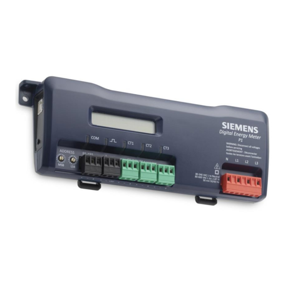
- Page 7 Current Transformers (CTs), Revenue Grade, Toroidal Solid Core Models; Quantity 1 50A, Revenue Grade, Toroidal Solid Core CT with 0.5” Window SCT-RGT12-0050-U 100A, Revenue Grade, Toroidal Solid Core CT with 05” Window SCT-RGT12-0100-U Figure 1: MD-P1 Power Meter Figure 2: MD-P1D Power Meter with Display Siemens Industry, Inc. 125-201 09/30/2019...
-
Page 8: Meter Anatomy
Safety Summary and Specifications This general safety information must be used by both the Logger operator and servicing personnel. Siemens Industry, Inc. assumes no liability for user’s failure to comply with these safety guidelines. The MD-BMS and MD-BMED Power Meters are Over-Voltage Category III devices. - Page 9 Before inspecting or servicing installed power meters, read and follow the Medium Risk, NFPA Category 2 PPE requirements (see NFPA 70E, Section 9.1, NFPA 70E PPE Selection Tables). WARNING MD-BMS, MD-BMED hazardous voltages exist. There are no user-serviceable parts inside. Do not open the enclosure. Siemens Industry, Inc. 125-201 09/30/2019...
-
Page 10: Sommaire Des Informations De Sécurité
Do not use other CTs. Only use shunted CTs with a 333 mV maximum output. Serious shock hazard and logger damage can occur if unshunted CTs are used. The UL listing covers the use of the following Siemens CTs that are UL Recognized and have been evaluated to IEC 61010-1: SCT-HSC-0050-U (50A Mini), SCT-HMC-0100- U (100A Midi), SCT-HMC-0200-U (200A Midi), SCT-RXX-A4-U (Rogowski Coil), SCT-SRS-xxx, SCT-SRL-xxx, and SCT-RGT12-xxx. - Page 11 Veuillez toujours utiliser un transformateur de tension pour des charges supérieures à 600 V. Le MD Power Meter est un appareil à 600 V avec protection contre les surtensions de catégorie III. Siemens Industry, Inc. 125-201 09/30/2019...
- Page 12 à l'enregistreur peuvent se produire si des transformateurs de tensions non shuntés sont utilisés. La certification UL couvre l’utilisation des transformateurs de tension de Siemens agréés UL et évalués sous IEC 61010-1 suivants : SCT‐HSC‐0050‐U, SCT‐HMC‐0100‐U, SCT‐HMC‐0200‐U, andSCT-RXX-A4-U.
-
Page 13: Md Power Meter Technical Specifications
Communication Data Format P1 FLN over RS-485 Network Maximum Distance 1200 meters Baud Rate 4800 baud (fixed, no adjustment) Data Bits Parity None Stop Bit RS 485 Transceiver unit load 1/8 Load size Siemens Industry, Inc. 125-201 09/30/2019... - Page 14 50 MB minimum available Processor Pentium Class 1 GHz or more recommended Safety Regulatory Agencies UL Listed to UL Standard 61010-1 an IEC61010-2-030 cUL certified to CAN/CSA Standard C22.2 No. 61010-1 CE Low Voltage and EMC Directives Siemens Industry, Inc. 125-201 09/30/2019...
-
Page 15: Maintenance
There is no required maintenance with the MD-P1 or MD-P1D Power Meters. CAUTION Do not use cleaning agents of any kind (including water) on the MD-P1 or MD-P1D Power Meters. Only accessories specified in Siemens product literature or price sheets are approved for use with MD-P1 or MD-P1D Power Meters. -
Page 16: Installation
Installation Maintenance Installation Figure 4: Power Meter Components and Connections. WARNING Remove the meter from all power sources before mounting. Siemens Industry, Inc. 125-201 09/30/2019... -
Page 17: Mounting The Md-P1 And Md-P1D Power Meters
Mounting the MD-P1 and MD-P1D Power Meters Mounting the MD-P1 and MD-P1D Power Meters The MD-P1 and MD-P1D Power Meters must be installed in an approved electrical panel or enclosure using proper installation practices according to the NEC and local electrical codes. -
Page 18: Completing The Wiring Connections - Rs-485, Voltage Leads And Cts
3. Tape back one of the FLN cable shields and connect the other shield to the Utility Panel Ground. 4. If the MD-P1 or MD-P1D is the last FLN device, install the end of line terminator on the positive (+) and negative (-) terminals. See APOGEE Wiring Guidelines for Field Panels and Equipment Controllers (125-3002) for additional information. - Page 19 After wiring FLN cable, remove all scraps of wire or foil shield from electrical utility panel. 7. Energize the MD-P1 or MD-P1D Power Meter. It is powered through the red power connector (see wiring connections in Figure 3). 8. Verify proper power meter operation. For normal operation, the RS-485 LED blinks.
- Page 20 Checking Phases for information about the CT LEDs and verifying the CT installation. When using the MD-P1 or MD-P1D Model Power Meter with Rogowski Coils (or CTs), unused CT input(s) should be shorted with a jumper wire if all three coils are not connected.
- Page 21 Follow local electrical codes during this installation. CAUTION Do not strap or mount an MD-P1 or MD-P1D Power Meter less than two inches from current carrying conductors. The magnetic field around the conductors may affect the electronics in the meter.
-
Page 22: Setting The P1 Address
Siemens P1-FLN protocol ONLY. These meters are designed to operate at a fixed 4800 baud rate. To communicate on the Siemens APOGEE BMS network, the meter must have a specific network address. The P1 network address switches are located on the front of the meters (see Figure 8). -
Page 23: Powering The Md-P1 And Md-P1D Power Meters
CT3 can be used if the blue L3 voltage lead is connected to either L1 or L2. If voltage leads L3 and CT3 are in-phase, the MD-P1 and MD-P1D Power Meters will provide correct kW readings. If the blue L3 voltage lead is connected to the L2 voltage source, then CT3 can monitor any L2 branch circuit. -
Page 24: System Values
System Values System values are the sum of L1 + L2 + L3 measurements. System values may not be meaningful since two different devices or loads can be monitored by a single MD-P1 or MD-P1D Power Meter element. When paired with the correct voltage phase, each CT provides individual kW/kWh readings for that CT channel. -
Page 25: Md-P1 And Md-P1D Power Meters Wiring Diagrams
MD-P1 and MD-P1D Power Meters Wiring Diagrams The MD-P1 and MD-P1D Power Meters can be wired using any one of the following five common wiring setups. These diagrams will assist you in properly connecting your power meter for the setup desired. - Page 26 Installation MD-P1 and MD-P1D Power Meters Wiring Diagrams WARNING Hazardous voltages exist. MD-P1 and MD-P1D Power Meters should only be wired by qualified personnel. Siemens Industry, Inc. 125-201 09/30/2019...
- Page 27 Installation MD-P1 and MD-P1D Power Meters Wiring Diagrams Siemens Industry, Inc. 125-201 09/30/2019...
- Page 28 Installation MD-P1 and MD-P1D Power Meters Wiring Diagrams Siemens Industry, Inc. 125-201 09/30/2019...
- Page 29 Installation MD-P1 and MD-P1D Power Meters Wiring Diagrams Siemens Industry, Inc. 125-201 09/30/2019...
-
Page 30: Supported P1 Applications
2679 Universal (scaling must be set at the job site) NOTE: If an MD-P1 or MD-P1D Power Meter is ordered as a spare, it will leave the factory configured for Application 2679. NOTE: If the P1 meter has firmware earlier than Revision 4.5, the application numbers use a number that is 100 higher (for example, Application 2671 was 2771). -
Page 31: Md-P1 Point Map By Application Number With Point Map Comparison
MD-P1 Point Map by Application Number with Point Map Comparison Table 4: MD-P1 Point Map by Application Number with Point Map Comparison to DEM1000, DEM2000 Point Type P1 Name Units Default Detail Slope Intercept MD-P1 MD-P1 DEM1000* DEM2000* Point Type... - Page 32 Point Type Default Slope Intercept MD-P1 MD-P1 DEM1000* DEM2000* P1 Name Units Detail Point Type Value for P1 for P1 Series** Series* Apps 710- Apps 717- Apps Apps Apps 2771- 2777 2779 - returns new value every min., will compare and post to min/max registers ∙...
- Page 33 Point Type Default Slope Intercept MD-P1 MD-P1 DEM1000* DEM2000* P1 Name Units Detail Point Type Value for P1 for P1 Series** Series* Apps 710- Apps 717- Apps Apps Apps 2771- 2777 2779 ∙ ∙ ∙ VOLTAGE A N Individual Phase L1 to Neutral Voltage ∙...
- Page 34 Point Type Default Slope Intercept MD-P1 MD-P1 DEM1000* DEM2000* P1 Name Units Detail Point Type Value for P1 for P1 Series** Series* Apps 710- Apps 717- Apps Apps Apps 2771- 2777 2779 = system max 500ms positive power draw value since reset (resettable) ∙...
- Page 35 Point Type Default Slope Intercept MD-P1 MD-P1 DEM1000* DEM2000* P1 Name Units Detail Point Type Value for P1 for P1 Series** Series* Apps 710- Apps 717- Apps Apps Apps 2771- 2777 2779 ∙ ∙ KVAR DEM MAX kVAR System Maximum Instantaneous...
- Page 36 Point Type Default Slope Intercept MD-P1 MD-P1 DEM1000* DEM2000* P1 Name Units Detail Point Type Value for P1 for P1 Series** Series* Apps 710- Apps 717- Apps Apps Apps 2771- 2777 2779 ∙ ∙ KVAH LO kVAh System Total Apparent Energy -...
- Page 37 Point Type Default Slope Intercept MD-P1 MD-P1 DEM1000* DEM2000* P1 Name Units Detail Point Type Value for P1 for P1 Series** Series* Apps 710- Apps 717- Apps Apps Apps 2771- 2777 2779 Power ∙ ∙ System Maximum Instantaneous KVA DEM MAX...
- Page 38 Point Type Default Slope Intercept MD-P1 MD-P1 DEM1000* DEM2000* P1 Name Units Detail Point Type Value for P1 for P1 Series** Series* Apps 710- Apps 717- Apps Apps Apps 2771- 2777 2779 not used not used ∙ ∙ PULSE1 CONF.
- Page 39 (kWh, kWh, and so on) stored in flash to CAM Default value. (off text = "ACC", on text = "CAM") ∙ ∙ ERROR STATUS * DEM P1 Applications 710 to 723 ** MD-P1 Series P1 Applications 2772 to 2779...
-
Page 40: Appendices
MD Model Power Meter. ● Upper rotary network address switch = high (first) digit ● Lower rotary network address switch = low (second) digit Table 5: Decimal to Hexadecimal Conversion. Decimal Hex Decimal Decimal Decimal Hex Decimal Decimal Siemens Industry, Inc. 125-201 09/30/2019... - Page 41 Appendices Appendix A - Decimal to Hexadecimal Conversion Table Decimal Hex Decimal Decimal Decimal Decimal Hex Decimal Siemens Industry, Inc. 125-201 09/30/2019...
-
Page 42: Appendix B - Ct Wire Lead Polarity
Appendix B - CT Wire Lead Polarity Table 6: CT Polarity. CT Type CT Lead + CT Lead - Rogowski White Brown Split Core mV White Black For Rogowski CTs, the arrow points toward the load (for example, motor). Siemens Industry, Inc. 125-201 09/30/2019... -
Page 43: Appendix C - Md-P1D With Visual Display
(default) timeout occurs, returning it to Auto Cycle. MANUAL CYCLE AND HOLD: The display will manually advance the flowchart screens by pushing the meter display button multiple times. The display screen will remain in its last displayed mode, updating values continuously. Siemens Industry, Inc. 125-201 09/30/2019... - Page 44 Appendices Appendix C - MD-P1D with Visual Display Siemens Industry, Inc. 125-201 09/30/2019...
-
Page 45: Appendix D - Monitoring And Servicing The Md-P1 And Md-P1D Model Power Meters
Perform firmware upgrades for MD-P1 and MD-P1D Power Meters. Obtaining and Installing ViewPoint Software The ViewPoint software is free to MD-P1 an MD-P1D Power Meter users. It is typically shipped on a flash drive with each order. It is also available for free download. To download and install the software: 1. -
Page 46: Connecting And Communicating Via A Usb Cable
It is recommended to use a Type AB USB cable between a personal computer and a MD-P1 or MD-P1D Power Meter to set up the meter. The USB cable will also power the meter when connected to a computer. When using a USB cable with a computer, each USB port on the computer generates a unique comm port in the ViewPoint software, such as Com3 or Com4 (see Figure 4.) - Page 47 Appendices Appendix D - Monitoring and Servicing the MD-P1 and MD-P1D Model Power Meters Communications Screen Figure 10: Communications Screen. To upload the MD-P1 or MD-P1D Power Meter information into the ViewPoint software: 1. From the pull down menu at the top right of this screen (Dec) PS24, select (Hex) PS3/PS3037.
- Page 48 Appendices Appendix D - Monitoring and Servicing the MD-P1 and MD-P1D Model Power Meters 2. From the PC COM Port drop-down menu, select USB. The screen updates with less information available to match MD-P1 or MD- P1D functionality. Siemens Industry, Inc.
- Page 49 Appendices Appendix D - Monitoring and Servicing the MD-P1 and MD-P1D Model Power Meters 3. Click the Connect button at the lower right corner of the screen. The meter’s key data is uploaded into the ViewPoint Service Software Tool, and displays the connected meter’s data on this screen including:...
- Page 50 Appendices Appendix D - Monitoring and Servicing the MD-P1 and MD-P1D Model Power Meters NOTE: There are no commands issued here; just data validation. Meter Setup Screen To verify the Current Transformer values that are pre-programmed as part of the meter's application, click the Meter Setup tab at the top of the ViewPoint Service software screen.
- Page 51 Appendices Appendix D - Monitoring and Servicing the MD-P1 and MD-P1D Model Power Meters This screen may initially be mostly blank. To upload your connected meter's CT selections defined by its programmed application, click on the Retrieve Meter Setup button at the bottom of the screen. The screen will update with information that is CT- dependent.
- Page 52 Appendices Appendix D - Monitoring and Servicing the MD-P1 and MD-P1D Model Power Meters There are three selections that must be verified on this screen: 1. Redefine the demand window, between 1 and 60 minutes by entering the desired number of minutes into the Demand Window box at the top of the screen.
- Page 53 Appendices Appendix D - Monitoring and Servicing the MD-P1 and MD-P1D Model Power Meters CAUTION DO NOT attempt to change CT values from this screen. CT values can only be updated by using the Siemens WCIS Programming Tool to modify the MD-P1 Model Power Meter application number.
-
Page 54: Appendix E - Installing Firmware Updates For The Md-P1 And Md-P1D Power Meter
1. Download the Zip file containing the firmware. Extract the Zip file to a folder on the computer. 2. Connect the computer to the MD-P1 or MD-P1D Power Meter using the USB port. See Installing the ViewPoint Software and Communicating with the MD Model Power Meter for additional information. -
Page 55: Comms Setup Screen
Comms Setup Screen This ViewPoint screen is designed for use with MD-BM BACnet/Modbus style power meters and is not applicable for the MD-P1 of MD-P1D Power Meter. It is strongly recommended not to use this screen for these power meters. -
Page 56: Verifying Installation With Viewpoint Software
Appendices Appendix E - Installing Firmware Updates for the MD-P1 and MD-P1D Power Meter CAUTION DO NOT make changes on this ViewPoint screen. Doing so may make the MD-P1 or MD-P1D Power Meter inoperable. Contact Siemens Technical Support for assistance before making meter register adjustments. - Page 57 This indicates the MD-P1 or MD-P1D Power Meter setup is correct. It may also be useful to use a handheld amp meter to test the current and compare its readings to the values provided on the Real-Time Values screen.
- Page 58 Read/Write Registers Screen This ViewPoint screen is designed for use with MD-BMS BACnet/Modbus style meters, and is not applicable for MD-P1 or MD-P1D Power Meters. It is strongly recommended that you do not use these screens for these meters. CAUTION DO NOT make changes on this ViewPoint screen.
-
Page 59: Appendix F - Measuring Consumption (Kwh), Demand, And Other Applications
((20 × 10000) – 7800) = 192200 February The following PPCL reads the MD-P1 and MD-P2 accumulators at the start of the specified time period (for example, month, week, and day) and stores them in virtual analog points. To calculate the consumption for a specified time period, a test is conducted where the most recent (that is, last) accumulator value is tested against the low accumulator reading taken at the start of the time period. - Page 60 C \NAME FOR THE CONSUMPTION FOR JULY ....(VLAO,JUL)\JUL\ 00242 C \NAME FOR THE CONSUMPTION FOR AUGUST ....(VLAO,AUG)\AUG\ 00244 C \NAME FOR THE CONSUMPTION FOR SEPTEMBER ....(VLAO,SEP)\SEP\ 00246 C \NAME FOR THE CONSUMPTION FOR OCTOBER ....(VLAO,OCT)\OCT\ Siemens Industry, Inc. 125-201 09/30/2019...
- Page 61 C ACTUAL DEM VALUES. OTHERWISE, SKIP AND CALCULATE THE MONTHLY VALUE. 02000 IF (DAYOFM .EQ. 1 .AND. CRTIME .EQ. 0.0) THEN GOTO 2010 ELSE GOTO 3000 02010 “%X%CMH” = “%Y%” 02020 “%X%CML” = “%Z%” 02994 02996 C CALCULATE THE PROPER MONTH 02998 Siemens Industry, Inc. 125-201 09/30/2019...
- Page 62 C IF IT IS 12:00 AM, THEN SET THE VIRTUAL METER CONSUMPTIION 03994 C POINTS EQUAL TO THE ACTUAL DEM VALUES. OTHERWISE, SKIP AND 03996 C CALCULATE THE DAILY VALUE. 03998 04000 IF (CRTIME .EQ. 0.0) THEN GOTO 4010 ELSE GOTO 5000 04010 “%X%CDH” = “%Y%” Siemens Industry, Inc. 125-201 09/30/2019...
- Page 63 IF (DAY .EQ. 7.0 .AND. CRTIME .GE. 23.99) THEN GOTO 6010 ELSE GOTO 7000 06010 “%X%CWH” = “%Y%” 06020 “%X%CWL” = “%Z%” 06994 06996 C CALCULATE THE PROPER WEEK. 06998 07000 SAMPLE(60) “%X%WEK” = (“%Y%” – “%X%CWH”) + (“%Z%” – “%X%CWL”) 10000 GOTO 1000 Siemens Industry, Inc. 125-201 09/30/2019...
-
Page 64: Measuring And Calculating Demand (Kw)
1% COV is needed for a 300 Amp service (300 Amps × Sqrt (3) × 480V/1000 = 249.6 kW ), select a COV of the slope × 20 (provides a COV every 0.064 slope × 20 kW = Siemens Industry, Inc. 125-201... -
Page 65: Trending Data
The following PPCL can be used for peak demand limiting applications: 00010 C ELECTRIC SUBMETER 00012 C THE SYSTEM WILL BE DDC CONTROLLED USING ELECTRIC ACTUATION. 00014 C NOTICE: ALL ACTUATORS ARE SET UP IN THE PROGRAM TO WORK AS 0% - 100% Siemens Industry, Inc. 125-201 09/30/2019... - Page 66 00030 C \WHAT IS THE SYSTEM NAME AND NUMBER? (SYSS)\SYSS\ 00032 00034 C THIS SOFTWARE IS OWNED AND MAINTAINED BY SIEMENS BUILDING TECHNOLOGIES, INC. 00036 C ALL RIGHTS RESERVED. ANY MODIFICATIONS WITHOUT THE EXPRESS, WRITTEN 00038 C CONSENT FROM SIEMENS BUILDING TECHNOLOGIES, INC. MAY VOID THE WARRANTY.
- Page 67 C NOTE: BRIEF: TOGGLE REGULAR EXPRESSIONS OFF (CNTRL F6) TO FIND %. 00998 01000 DEFINE(X,”%X%”) 01010 DEFINE(U,”DEM:DEMAND”) 01094 01096 C SUBMETER ACTUAL READING 01098 01100 %X%KW = $PDL 01194 01196 C MONITOR OF THE SUBMETER 01198 01200 PDLMTR (”%X%ARE”, ”%X%HST”, ”%X%CLC”, ”%X%WND”, ”%X%PLT”,0,”%U%”,-1) 01294 Siemens Industry, Inc. 125-201 09/30/2019...
-
Page 68: Data Reliability
Power Failure On power failure, the power meter retains the last observed kWh value in nonvolatile memory. All other values are instantaneous in nature and not stored during power failure. Siemens Industry, Inc. 125-201 09/30/2019... -
Page 69: Appendix G - Md-P1D With Visual Display
A Hold button (located on the side of the meter near the USB jack) will stop the cycle until it is pressed again or a set timeout is reached The following flowchart shows the information displayed during the cycles. Siemens Industry, Inc. 125-201 09/30/2019... - Page 70 Appendices Appendix G - MD-P1D with Visual Display Siemens Industry, Inc. 125-201 09/30/2019...
- Page 71 Manual Cycle and Hold: The display will manually advance the flowchart screens by pushing the meter display button multiple times. The display screen will remain in the last displayed mode, updating values continuously. Siemens Industry, Inc. 125-201 09/30/2019...
-
Page 72: Frequently Asked Questions - Faqs
See the Installation section for detailed setup information. How many MD-P1 or MD-P1D Power Meters can be connected together? Up to 20 MD-P1 or MD-P1D Power Meters can be connected together on a P1 FLN network. How is hexadecimal (HEX) to decimal converted? Use the Decimal to Hexadecimal Conversion table in Appendix A of this manual. -
Page 73: Glossary
A multiplier that changes amperage so that a meter can read higher measurements. Analog Value A type of BACnet object that is a floating point number. On the MD-P1 and MD- P1D Model Power Meters, Analog Value objects are used to represent the electrical measurements. - Page 74 Supervisory Control And Data Acquisition. It generally refers to an industrial control system: a computer system monitoring and controlling a process. Service A BACnet service is a message that the MD-P1 and MD-P1D Power Meters must respond to. In BACnet these include WhoIs, I-Am, and ReadProperty. Volts Multiplier A multiplier that changes voltage so that a meter can read measurements higher than 600V.
- Page 75 Glossary Siemens Industry, Inc. 125-201 09/30/2019...
- Page 76 © Siemens Industry, Inc., 2019 Siemens Industry, Inc. Technical specifications and availability subject to change without notice. Smart Infrastructure 1000 Deerfield Pkwy Buffalo Grove IL 60089 Tel. +1 847-215-1000 Document ID 125-201 125-201(DA) MD-P1 and MD-P1D Model Power Meters Edition 09/30/2019...
Need help?
Do you have a question about the MD-P1 and is the answer not in the manual?
Questions and answers