Table of Contents
Advertisement
Advertisement
Table of Contents

Subscribe to Our Youtube Channel
Related Manuals for Crowcon Gasman


Summary of Contents for Crowcon Gasman
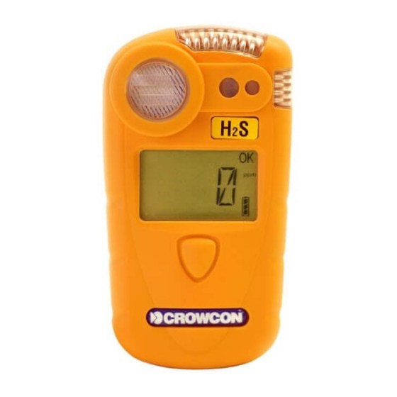
- Page 1 Gasman Personal Gas Monitor User Manual M07630 October 2008 Issue 7...
-
Page 2: Safety Information
The rechargeable battery must only be charged in non-hazardous (safe) areas by connection to the specified Crowcon charger. Only the following cell types may be fit- ted in the battery compartment of the... - Page 3 The equipment is not certified for use in ment may be photocopied, reproduced, or atmospheres containing more than 21% translated to another language without the oxygen. prior written consent of Crowcon Detection Area Classifications: - Instruments Ltd. Publication number: M07630 Zone 1:...
-
Page 5: Table Of Contents
Gasman Personal Gas Monitor Contents Unpacking ........1 Quickstart guide . -
Page 7: Unpacking
However, if this is the first time you have used the Gasman unit, you may need to charge the battery to attain the full operating time. (The actual operat- ing time will depend on the types of sensor installed.) The flammable... - Page 8 Non-rechargeable units. Gasman uses a CR2 battery which can be easily field replaced. Ensure only the correct types of battery are fitted to maintain compliance with certification.
-
Page 9: Quickstart Guide
Operator LCD Button Display Screen Switching on your unit Gasman requires little setting up, follow these simple steps to get your unit ready for use. 1. Ensure the unit is in clean air. 2. Switch on Press and hold the operator button for approximately 3 seconds until the red LEDs flash. - Page 10 ‘ZERO’ and ‘????’. Press the operator button with a single click to confirm Zero. If the operator button is not pressed within the 10 second time out, Gasman will proceed directly to Run mode without performing Zero. Autozero confirm...
- Page 11 AL - 2 — Alarm level two 1. When the gas level returns to normal, press the operator button. This will reset your Gasman unit to normal Run mode. If the gas level is still in alarm, the button will have no effect.
- Page 12 Quickstart guide Gasman Storing conditions In order to optimise sensor performance and lifetime, your Gasman unit should be stored in a safe, non-hazardous area, 0-30°C, 10-90%RH. 4. Additional information For battery recharging information go to section III. For fixing accessories go to section V.
-
Page 13: Introduction
Gasman has been designed from top to bottom to bring you a lighter, compact design with single button operation for ease of use, mainte- nance and extreme reliability. - Page 14 Reliable, anti-shock mechanics and robust housing The Gasman housing is built from resilient material, giving it strength and flexibility to withstand the hardest of working conditions, water and dust tight to IP65 and IP67, with a non-slip grip. If the unit is dropped, there will be no disruption of power or function, ensuring reliability and service for years to come.
-
Page 15: Operation
20.9%. If the operator button is not pressed within 10 seconds Gasman will proceed directly to normal operation without performing a zero. Switch off To switch off the unit, press and hold the operator button for 5... - Page 16 If the battery becomes too low, Gasman will switch off. TWA alarm Gasman will display the TWA alarm when the 15 minute or 8 hour time weighted average alarm threshold is passed for toxic gases. Gasman will display ‘LTWA’ and ‘STWA’. TWA alarms cannot be cleared.
- Page 17 2. Press the operator button with a single click to scroll across the list. When the underscore appears under your choice, double-click the operator button. If Peak or TWA is selected, Gasman will display the icon on the operator screen.
- Page 18 Data is recorded every minute (this rate can be adjusted using the PC software). The log can record 900 hours of data at 1-minute intervals. Gasman also records the time and date for a number of operating and diagnostic events including: •...
-
Page 19: Batteries
3.2 Gasman Charging Unit There are 3 models of charging units available for Gasman; a sin- gle way drop in charger unit, a single way charger unit with integral PC Interface, and a multiway charger unit. The multiway charger unit can accommodate up to 5 Gasman units. - Page 20 It is recommended that rechargeable batteries should be changed by an authorised Crowcon service centre. 3.3 Non-rechargeable batteries Gasman uses a Lithium Cell battery pack which will give up to two years of operation. Always switch the Gasman off before opening the case to change the battery. To replace the battery pack, ensure you are in a safe, non-hazardous area.
-
Page 21: Alarm Indications
In the event of a Time Weighted Alarm (TWA) In the event the 15 minute or the 8 hour TWA is triggered, Gasman will go into alarm and display a TWA warning with the toxic gas readings. The 8 hour TWA alarm cannot be... - Page 22 In the event of a Flammable overange alarm If flammable gas concentrations exceed 100% LEL Gasman locks into alarm and displays ‘9999’ showing an overange condition. Gasman will temporarily cut off power to the sensor to prevent burn out and display a progress bar for 200 seconds.
-
Page 23: Fixing Accessories
Clip Accessories Gasman is supplied with a simple pocket clip, other clip options are: Hard hat clip Allows Gasman to be clipped to a hard hat, a method of wearing a port- able gas detector preferred by many users. Alligator clip A strong alligator clip allowing the user to wear Gasman on a belt, sleave, jacket lapel etc. -
Page 24: Flow Sampling
Gasman VI. Flow sampling Attaching the flow cap To perform manual sampling using Gasman, a flow cap must be fitted onto the front of the unit, over the sensor. A flow cap is included with your Gasman unit. 1. To fit the flow cap, slip the flow cap over the sensor on the front of your Gasman unit, until the cap is tightly fitted into place. - Page 25 'Trigger' regulator with interconnect tubing, a magnet - used to activate Test mode, a flow cap to attach to the Gasman, and a vent line. The kit is supplied in a convenient carry case. The Trigger regulator can be operated in two ways: (1) squeeze and hold - allows gas flow as long as the lever is held in, or (2) by lifting the lever - the flow is locked on.
- Page 26 4. To abort the Calibration test press the button at any time whilst the test is in progress. Your Gasman unit will adjust the value for the gas channel to match the stored calibration gas value within the sensor i-module.
- Page 27 Note: Remove regulator from gas cylinder when not in use over a pro- longed period. For parts list, see section XI. One button Calibration will check for small drifts of stored calibration value, but Crowcon recommends Gasman is sent for full certified calibra- tion at six monthly intervals.
-
Page 28: Maintenance And Calibration
Instrument calibration of sensor should be performed at 6 month regular intervals. Calibration method Gasman calibration can be performed using the Gas Test Kit as per 6.3, or with Crowcon Portables PC software and calibration gas mixtures. Appropriate certified calibration gases should be used. Calibration gas is applied using the appropriate flow cap. - Page 29 CO emissions, and holding the unit well away from the breathing zone of the operator – i.e. at arm’s length. When Gasman IR CO is zeroed in fresh air it automatically sets the CO baseline level to 0.04%.
-
Page 30: Pc Interface And Software
Gasman VIII. PC interface and software Gasman can be connected to a PC using the single way charger unit with optional PC interface. The charger unit is fitted with a D-type 9 pin RS232 socket which is located at the rear of the charger, see diagram below. The PC requires Crowcon Portables PC software. -
Page 31: I-Module Replacement
i-module 3. Place the Gasman unit face down on a surface. 4. Unclip the i-module from its retaining support clip. Ease one side out at a time. Ensure the elastomer which is retained within the body of the support clip remains in place. - Page 32 7. Replace the back of the Gasman case. 8. Switch on the Gasman unit. The new i-module will be automatically recognised. 9. Crowcon advise carrying out a calibration check when any new sensor...
-
Page 33: Specification
Gasman Specification X. Specification Dimensions 90 x 48 x 24 mm (3 x 1.9 x 1 inches) Weight 130 g flammable 105 g oxygen 90 g toxic Housing, degree of protection Ingress protection IP65 (NEMA 4) & IP67 Operating temperature -20°C to +55°C (-4°F to +131°F) - Page 34 Specification Gasman Standards Safety: EN60079-0, EN60079-1, EN60076-11, 94/9/EC USA: UL913 Canada: CSA22.2, 152 Operation EN50270, EN50271, IEC61508, EN61779...
-
Page 35: Accessories And Spare Parts
Gasman Accessories and spare parts XI. Accessories and spare parts Accessory list Crowcon part number Description Single way chargers C01941 12 V DC input single way charger C01942 Single way charger with 230 V UK style power supply C01943 Single way charger with 230 V EUR style power supply... - Page 36 0-100 ppm ammonia S011438 0-1000 ppm ammonia S011431 0-5 ppm phosphine S011434 0-1 ppm fluorine S011433 0-10 ppm hydrogen fluoride S012015 Gasman IR CO i-module Sampling accessories: M02340 Alligator Clip M04851 Flow cap C01937 Aspirator Assembly Calibration gas contact Crowcon...
-
Page 37: Troubleshooting Guide
Gasman Troubleshooting guide XII. Troubleshooting guide Symptom/ Cause Action error message Instrument won't switch on Flat battery Recharge or replace battery. No confidence beep Function disabled Reconfigure with PC software. Gas reading when no gas Zero drifted Restart instrument in clean present air. -
Page 38: Appendix: Limitations Of Sensors
Appendix: Limitations of sensors Sensor limitations The sensors used in Gasman have limitations common to all such gas sensors, and users should be aware of the points listed below. Crowcon can advise on particular situations and suggest alternative sensors if the instrument is likely to experience extreme conditions. - Page 41 Thank you for reading this data sheet. Please contact us for a quotation: Head Office (UK) Switzerland Office P.O. Box 2124 Zugerstrasse 46 Chelmsford 6314 Unterägeri Essex CM1 3UP England Switzerland Tel: +44 (0)1245 600 560 Tel: +41 41 541 5877 Fax: +44 (0)1245 600 030 Fax: +41 41 541 5878 Email:...
Need help?
Do you have a question about the Gasman and is the answer not in the manual?
Questions and answers