Table of Contents
Advertisement
Advertisement
Table of Contents

Related Manuals for Crowcon Gasman

Summary of Contents for Crowcon Gasman
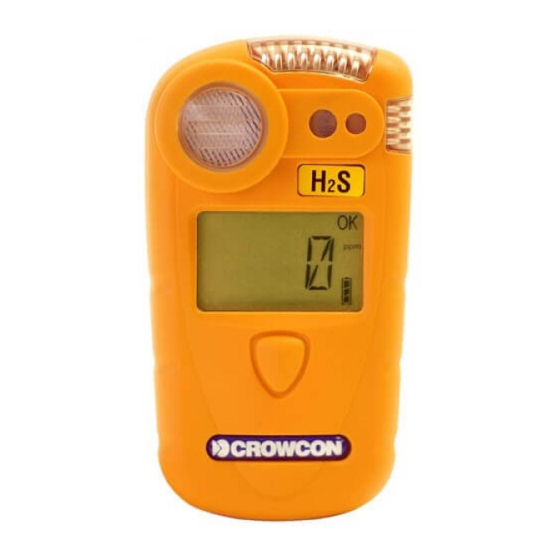
- Page 1 Gasman Personal Single Gas Monitor User Manual M07630 Sep 2015 Issue 11...
- Page 2 The rechargeable battery must only be charged in non-hazardous (safe) areas by connection to the specified Crowcon charger. Only the following cell types may be fitted in the battery compartment of the...
- Page 3 Ltd 2015. All rights are reserved. No part of the docu- ment may be photocopied, reproduced, or translated to another language without the prior written consent of Crowcon Detection Instruments Ltd. Safety information: • Read and understand all instructions in the operation section of this manual before use.
-
Page 5: Table Of Contents
Gasman Personal Single Gas Monitor Contents Unpacking ........1 I. -
Page 7: Unpacking
However, if this is the first time you have used the Gasman unit, you may need to charge the battery to attain the full operating time. (The actual operating time will depend on the types of sensor installed.) The... - Page 8 Section X is not applicable. Operation and maintenance of the Gasman IR CO is essentially the same as for other Gasman units but with the following points to note.
- Page 9 Button Display Screen Switching on Gasman requires little setting up. Follow these simple steps to get your unit ready for use. 1. Ensure the unit is in clean air. 2. Switch on. Press and hold the operator button for approximately 3 seconds until the red LEDs flash.
- Page 10 Vibrator Alarm test The Gasman screen will show the following display during the warm up sequence. This will take approximately 20 seconds. vv/v Note: these screens may differ depending on what sensor is being used.
- Page 11 Quickstart guide Confidence signals In normal Run mode, Gasman will emit a short beep accompanied by a blue LED flash every 10 seconds and the OK icon flashes to show operational health. These confidence signals can be disabled using the PC software.
- Page 12 Quickstart guide Gasman Storing conditions In order to optimise sensor performance and lifetime, your Gasman unit should be stored in a safe, non-hazardous area, at 0-20°C and 20-90% 4. Additional information For battery recharging information go to section III. For fixing accessories go to section V.
-
Page 13: Introduction
LEDs and an internal vibrator. Gasman can be fitted with a wide range of modular, or plug and play gas sensors. The sensor carries an intelligent processor which contains calibration and sensor information. - Page 14 Reliable, anti-shock mechanics and robust housing The Gasman housing is built from resilient material, giving it strength and flexibility to withstand the hardest of working conditions, water and dust tight to IP65 with a non-slip grip. If the unit is dropped, there will be no disruption of power or function, ensuring reliability and service for years to come.
-
Page 15: Operation
Press the button to continue to Run mode. The Gasman can be set, using Portables PC software, to lock out in the event of the calibration due date expiration in order to prevent further operation of the detector until a calibration is preformed. - Page 16 Peak and TWA readings, go to section 2.4. Confidence signals To reassure users the unit is working correctly, the Gasman unit will emit a short confidence beep accompanied by a blue LED flash every 10 seconds and the OK icon will flash continuously.
- Page 17 2. Press the operator button with a single click to scroll across the list. When the underscore appears under your choice, double-click the operator button. This will select the option. If Peak or TWA is selected, Gasman will display the icon on the operator screen.
- Page 18 When Zero is completed, the instrument will return to normal Run mode. 3. Run mode The Gasman is now ready to use. Familiarise yourself with the gas being monitored in your unit and make sure you understand site health and safety procedures in the...
- Page 19 Data is recorded every minute (this rate can be adjusted using the PC software). The log can record 900 hours of data at 1-minute intervals. Gasman also records the time and date for a number of operating and diagnostic events including: • Switch on and switch off;...
-
Page 20: Batteries
3.2 Gasman Charging Unit There are 3 models of charging units available for Gasman; a single way drop in charger unit, a single way charger unit with integral PC Interface, and a multiway charger unit. The multiway charger unit can accommodate up to 5 Gasman units. - Page 21 Note: When a non-rechargeable detector is placed in the charger/charger interface the red LED will not illuminate and the detector will not charge. * Note: later versions of the Gasman will have a tab in place to aid removal of the battery.
-
Page 22: Alarm Indications
Gasman IV. Alarm indications Gasman provides two instantaneous alarm levels, designated level 1 and level 2. For toxic gas sensors, there are also two TWA alarms, one for short term exposure (STEL): based on a 15 minute time weighted average, and the second TWA alarm is for long term exposure (LTEL): based on a 8 hour time weighted average. - Page 23 This option is programmable with Crowcon Portables PC software and the default is switched on. If the Gasman goes over range at any time it is recommended to carry out a gas test before using it again.
-
Page 24: Fixing Accessories
Clip Accessories Gasman is supplied with an alligator clip. Other clip options are: Hard hat clip Allows Gasman to be clipped to a hard hat, a method of wearing a portable gas detector preferred by many users. Pocket Clip Allows Gasman to be clipped to a pocket, near the breathing zone of the user. -
Page 25: Flow Sampling
Gasman instrument. When using an extended length of tubing a response time test is recommended. Gas of known concentration should be sampled along the full length of tubing to be used and the time taken for the sensor reading to reach the known gas levels should be noted. - Page 26 'Trigger' regulator with interconnect tubing, a magnet - used to activate Test mode, a flow cap to attach to the Gasman, and a vent line. The kit is supplied in a convenient carry case. The Trigger regulator can be operated in two ways: (1) squeeze and hold - allows gas flow as long as the lever is held in, or (2) by lifting the lever - the flow is locked on.
- Page 27 To perform a one button Calibration, complete the next steps within 15 minutes of completing the Zero. 2. Follow steps 1 to 3 given in 6.2, Gasman will display ‘CAL’ and ‘????’ alternately. Press the button to confirm one button Calibration.
- Page 28 This will cause the gas to leak. For parts list, see section XI. One button Calibration will check for small drifts of stored calibration value, but Crowcon recommends Gasman is sent for full certified calibration at six monthly intervals.
-
Page 29: Maintenance And Calibration
Instrument calibration of sensor should be performed at 6 month regular intervals. Calibration method Gasman calibration can be performed using the Gas Test Kit as per 6.3 or with Crowcon Portables PC software and calibration gas mixtures. Appropriate certified calibration gases should be used. Calibration gas is applied using the appropriate flow cap. - Page 30 CO emissions. Hold the unit well away from the breathing zone of the operator – i.e. at arm’s length. When Gasman IR CO is zeroed in fresh air it automatically sets the CO baseline level to 0.04%.
- Page 31 The standard flow plate should be used to supply gas at the flow rate stated above. If required your local Crowcon representative or service centre will be able to provide further advice.
-
Page 32: Pc Interface And Software
Gasman VIII. PC interface and software Gasman can be connected to a PC using the single way charger unit with optional PC interface. The charger unit is fitted with a D-type 9 pin RS232 socket which is located at the rear of the charger, see diagram below. The PC requires Crowcon Portables PC software. A USB-RS232 adaptor is also... - Page 33 The Gasman is capable of storing 54,000 logs (>4,800 events). When the memory is filled, new data then overwrites the oldest data. A log can be extracted from the Gasman and saved using Portables PC software. The instrument will record the following events: • Switch on/off...
-
Page 34: I-Module Replacement
i-module Elastomer 3. Place the Gasman unit face down on a surface. 4. Unclip the i-module from its retaining support clip. Ease one side out at a time. Ensure the elastomer which is retained within the body of the support clip remains in place and should not be touched by hand. - Page 35 7. Replace the back of the Gasman case and secure with screws. 8. Switch on the Gasman unit. The new i-module will be automatically recognised.
-
Page 36: Specification
Specification Gasman X. Specification Dimensions 90 x 48 x 24 mm (31/2 x 1.9 x 1 inches) Weight 138 g flammable 129 g oxygen 118 g toxic Housing, degree of Ingress protection IP65 (NEMA 4) protection Operating temperature -20°C to +55°C (-4°F to +131°F) -
Page 37: Accessories And Spare Parts
Gasman Accessories and spare parts XI. Accessories and spare parts Accessory list Crowcon part number Description Single way chargers C01941 Single way charger 12Vdc input C011318 Single way charger with multi-region power supply C011011 Single way charger 230V in-line power supply, no plug... - Page 38 0-5% Gasman IR (carbon dioxide) CO i-module (for use in safe areas only) Sampling accessories: M04852 Flow cap C01937 Aspirator Assembly Calibration gas contact Crowcon - required gases depend on sensor combination Carrying and wearing: C01952 Harness Plate C01843 Shoulder Strap C01844...
- Page 39 Gasman Accessories and spare parts M04973 Gasman front and rear moulding set E01918 Non-rechargeable Battery E07621 i-module Elastomer E07620 LCD Elastomer M04682 Sensor Sealing Ring M03705 Clip retaining nut M3 M03793 Case screw M05910 Crowcon domed label E01552 Power Supply for charger - 230 V No plug...
-
Page 40: Troubleshooting Guide
Accessories and spare parts Gasman XII. Troubleshooting guide Symptom/ Cause Action error message Instrument won't switch on Flat battery Recharge or replace battery. No confidence beep Function disabled Reconfigure with PC software. Gas reading when no gas Zero drifted Restart instrument in clean present air. -
Page 41: Appendix: Limitations Of Sensors
Appendix: Limitations of sensors Sensor limitations The sensors used in Gasman have limitations common to all such gas sensors, and users should be aware of the points listed below. Crowcon can advise on particular situations and suggest alternative sensors if the instrument is likely to experience extreme conditions. - Page 44 UK Office Singapore Office Crowcon Detection Instruments Ltd Crowcon Detection Instruments Ltd 172 Brook Drive, Block 194, Pandan Loop Milton Park, #06-20 Pantech Industrial Complex Abingdon Singapore 128383 Oxfordshire Tel: + 65 6745 2936 OX14 4SD Fax: +65 6745 0467 Tel: +44 (0) 1235 557700 Email: sales@crowcon.com.sg...
Need help?
Do you have a question about the Gasman and is the answer not in the manual?
Questions and answers