Advertisement
Quick Links
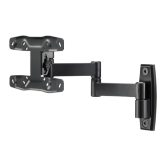
SAN213
(6904-002011<01>)
Wood
Concrete
Solid or Block
13mm
5.5mm
10mm
(1/2 in.)
(7/32 in.)
(3/8 in.)
Sanus Systems
2221 Hwy 36 West
Saint Paul, MN 55113 USA
Customer Service
Americas: 800-359-5520 • 651-484-7988 • info@sanus.com
Europe, Middle East, and Africa: + 31 40 2324700 • europe.sanus@milestone.com
Asia Pacifi c: 86 755 8996 9226 • sanus.ap@milestone.com
accents.sanus.com
©2010 Milestone AV Technologies, a Duchossois Group Company.
All rights reserved. Accents is a Milestone brand.
All other brand names or marks are used for identifi cation purposes and are trademarks of their respective owners.
Advertisement

Subscribe to Our Youtube Channel
Related Manuals for Sanus SAN213


Summary of Contents for Sanus SAN213
- Page 1 Saint Paul, MN 55113 USA Customer Service Americas: 800-359-5520 • 651-484-7988 • info@sanus.com Europe, Middle East, and Africa: + 31 40 2324700 • europe.sanus@milestone.com Asia Pacifi c: 86 755 8996 9226 • sanus.ap@milestone.com accents.sanus.com ©2010 Milestone AV Technologies, a Duchossois Group Company.
- Page 2 WARNING: This product Solid Concrete and Concrete Wood stud walls Choose an Option Do Not contains small items that could Block Mounting be a choking hazard. Caution / Warning Heavy! Assistance Required. Unlock/Lock This End Up Tools required 6904-002011<01>...
- Page 3 59.2 mm 2.33 in. 180° 360º 230 mm 9.06 in. 200 mm 7.87 in. 100 mm 3.94 in. 75 mm 2.95 in. 75 mm 100 mm 2.95 in. 3.94 in. 169.3 mm 6.67 in. 256.1 mm 10.08 in. 318.3 mm 12.53 in.
- Page 4 CAUTION: IMPORTANT SAFETY INSTRUCTIONS – SAVE THESE INSTRUCTIONS – PLEASE READ ENTIRE MANUAL BEFORE USING THIS PRODUCT Specifi cations Weight capacity-DO NOT EXCEED: 20.5 kg (45 lbs) includes TV and any accessories CAUTION: Avoid potential personal injuries and property damage! ...
- Page 5 [01] x 1 [02] x 1 5/16 x 2 ½ in. 1/4-20 x 3 ¼ in. [03] x 2 [04] x 2 [05] x 1 1/4-20 in. 0.5 in. 0.5 in. [06] x 1 [07] x 1 [08] x 1 [09] x 1 [10] x 2 8-32 x 0.5 in.
- Page 6 For TVs with a fl at/unobstructed back. Ensure that the bracket is level on the back of the TV. Standard confi gurations are shown. If you need extra space to accommodate cables, recesses, or protrusions, see installation option 1-2 that uses spacers. For special applications, or if you are uncertain about your [02] hardware selection, contact Customer Service.
- Page 7 6904-002011<01>...
- Page 8 CAUTION: Wall Mounting 2-1: Wood Stud Mounting CAUTION: Improper use could reduce the holding power of the lag bolt. To avoid potential injuries or property damage: Pilot holes MUST be drilled to a depth of 63.5 mm (2.5 in.), using a 5.5 mm (7/32 in.) diameter drill bit. ...
- Page 9 13mm 5.5mm (1/2 in.) (7/32 in Wood Stud Wall Mounting – See Cautions in Step 2. Locate stud. Verify the center of the stud with an awl or thin nail or use an edge to edge stud fi nder. Level the wall plate [01] and mark the hole locations. Drill pilot holes as illustrated.
- Page 10 13mm 10mm (1/2 in.) (3/8 in. Solid Concrete and Concrete Block Mounting – See Cautions in Step 2. Level wall plate and mark the hole locations. Drill pilot holes as illustrated. Insert lag bolt anchors [04]. Place the wall plate against the wall. Tighten lag bolts [03] only until they are pulled fi rmly against the wall plate [01]..
- Page 11 Fit nut [08] and cover [16] into underside of mount arm [01]. Place washer [07] and pivot pin [06] onto mount arm. Heavy: You will need assistance with this step! Fit mounting bracket [18] [02] onto pivot pin [06]. Slide washers [10] and spacer [09] onto mounting bolt [05] and fi t bolt through mounting bracket [02] and pivot pin [06] until it meets nut [08].
- Page 12 Arrange Cables and Add Plates NOTE: Pull the arm to its full extension before routing the cables through the channels, then loosely route the cables. This will give the cables enough slack to prevent excess tension when adjusting the position of the arm. [01] [14] [15]...
-
Page 13: Top View
Adjust arm extend / retract tension Adjust left / right swivel tension Adjust up / down tilt tension SIDE VIEW TOP VIEW [18] [18] SIDE VIEW 6904-002011<01>... - Page 14 Milestone AV Technologies and its affi liated corporations and subsidiaries (collectively, “Milestone”), intend to make this manual accurate and complete. However, Milestone makes no claim that the information contained herein covers all details, conditions, or variations. Nor does it provide for every possible contingency in connection with the installation or use of this product.
Need help?
Do you have a question about the SAN213 and is the answer not in the manual?
Questions and answers