
Subscribe to Our Youtube Channel
Related Manuals for Sanus SLF9


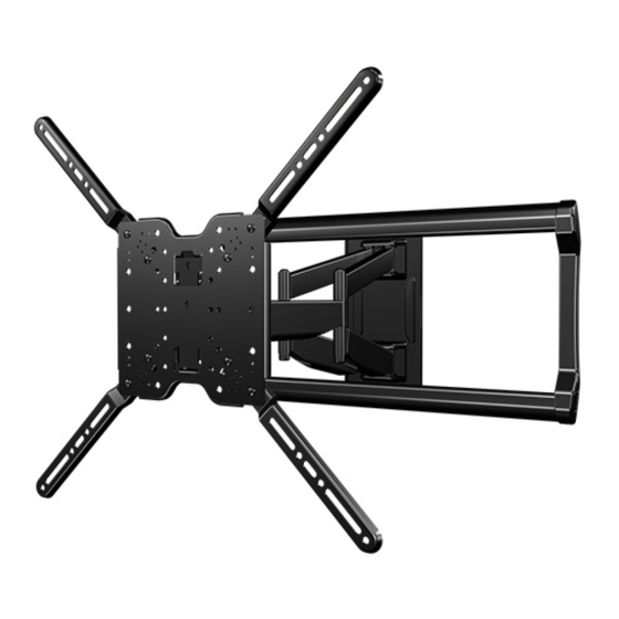
Summary of Contents for Sanus SLF9
- Page 1 SLF 9 INSTRUCTION MANUAL We’ll Make It Stress-Free If you have any questions along the way, just give us a call. 1-888-333-1376 (UK: 0800-056-2853). We’re ready to help! Scan for easy install video http://san.us/1043...
- Page 2 Does your TV No — Perfect! (including accessories) 150 lbs. weigh more than Yes — This mount is NOT compatible. Visit simplicity.sanus.com or call 1-888-333-1376 (68 kg) 150 lbs. (68 kg)? (UK: 0800-056-2853) to find a compatible mount. What is your...
- Page 3 Features Adjustment knob allows fingertip control of TV or restriction of TV movement Fully articulating arm with 3 pivot points, creates Level optimal viewing positions adjustment creates a worry-free installation Fit TV VESA hole patterns from 75 x 75 mm up to 600 x 400 mm TV tilts up or down for...
- Page 4 Dimensions 3-D VIEW TV INTERFACE 23.62 in [600mm] 15.75 in [400mm] 3.9 in [100mm] 15.75 in 7.87 in [400mm] [200 mm] 3.0 in [750 mm] 2.95 in [750 mm] 3.9 in [100mm] 7.87 in [200 mm] WALL PLATE TOP VIEW - EXTENDED SIDE VIEW - EXTENDED 16 in [406 mm]...
-
Page 5: Step 1 Attach Bracket To Tv
STEP 1 Attach Bracket to TV Parts and Hardware for STEP 1 WARNING: This product contains small items that could be a choking hazard if swallowed. Before starting assembly, verify all parts are included and undamaged. If any parts are missing or damaged, do not return the damaged item to your dealer; contact Customer Service. Never use damaged parts! NOTE: Not all hardware included will be used. - Page 6 1.1 Measure Your TV Hole Pattern Measure the width and height of your TV hole pattern in mm. Record your measurements for STEP 1.2. idth _____________ mm X eight _____________ mm 75 mm = 7.5 cm ≈ 3 in. 100 mm = 10 cm ≈ 4 in. 200 mm = 20 cm ≈...
- Page 7 1.2 Assemble Your TV Bracket [mm] [mm] Based on your TV hole pattern measurements from STEP 1.1 ( ), determine your 300 x 300 mm 400 x 300 mm TV bracket configuration: A, B, C, D, E or F. 400 x 400 mm 15.75 [400] 15.75...
- Page 8 [mm] [mm] [mm] 600 x 400 mm 400 x 200 mm 200 x 400 mm 23.62 [600] 15.75 [400] 7.87 [200] 15.75 7.87 [400] [200] 15.75 [400] Assemble TV bracket extenders onto Assemble TV bracket extenders onto Assemble TV bracket extenders onto TV bracket and secure using eight...
- Page 9 1.4 TV Screw Length 1.3 TV Screw Diameter If your TV included inset spacers or wall mount adapters, see Troubleshooting Hand thread screws into the : If your TV has a : Spacers and longer screws are threaded inserts on the back of flat back AND you supplied to accommodate: PAGE 25.
- Page 10 1.5 Attach TV Bracket Position your TV bracket configuration (A, B, C, D, E or F) onto your TV, making sure the bracket is both centered and level over your TV hole pattern. NOTE: The hanging tab on TV bracket must be oriented toward the top of the TV.
-
Page 11: Step 2 Attach Wall Plate To Wall
STEP 2 Attach Wall Plate to Wall Parts and Hardware for STEP 2 Wall Plate Template Lag Bolts TH IS W AY 5/16 x 3 1/2 in. W E L C O M E A N D T H A N K S F O G E T S TA R... -
Page 12: Wood Stud Installation
● Drywall covering the wall must not exceed 5/8 in. (16 mm) HeightFinder at Simplicity.Sanus.com ™ ● Minimum wood stud size: common 2 x 4 in. (51 x 102 mm) nominal 1 ½ x 3 ½ in. (38 x 89 mm) ●... - Page 13 Drill pilot holes using a 7/32 in. (5.5 mm) diameter drill bit, then remove the wall plate template IMPORTANT: Be sure to drill into the center of the stud. IMPORTANT: Pilot holes must be drilled to a depth of 3 1/2 in. (89 mm). Install the wall plate using four lag bolts and four washers...
- Page 14 ● Mount the wall plate directly onto the concrete surface HeightFinder at Simplicity.Sanus.com ™ ● Minimum solid concrete thickness: 8 in. (203 mm) ● Minimum concrete block size: 8 x 8 x 16 in. (203 x 203 x 406 mm) ●...
- Page 15 Remove the wall plate template and insert six concrete anchors (two on the bottom, four on top). CAUTION: Be sure the anchors are seated flush with the concrete surface. Install the wall plate using six lag bolts and six washers (two on the bottom, four on top).
-
Page 16: Step 3 Attach Tv To Wall Plate
STEP 3 Attach TV to Wall Plate Hardware for STEP 3.2 Parts and Hardware for STEP 3.1 Locking Screw 1/4-20 x 5/8 in. Arm Assembly 1/4-20 x 5/8 in. 1/4-20 x 5/8 in. 1/4-20 x 5/8 in. Parts for STEP 3.3 Cable Covers 22mm Parts and Hardware for STEP 3.4... - Page 17 3.1 Attach Arm Assembly to Wall Plate Position the arm assembly on the wall plate by tilting the top into the wall plate channel , then rotating the bottom toward the wall. CAUTION: Avoid potential injury or property damage! For concrete applications, the base of the arm must remain centered in the wall plate NOTE: When mounting to wood stud walls, arm assembly can be adjusted within the wall plate...
- Page 18 Secure with four wall plate screws and four washers using hex key CAUTION: Avoid potential personal injury or property damage! Screws and washers must be installed to secure arm assembly to wall plate Pull arm assembly to full extension.
- Page 19 3.2 Attach TV to Arm Assembly HEAVY! You may need assistance with this step. Hang the TV onto the arm assembly by first hooking the hang tab , then resting the TV into place. Lock the TV to the arm assembly with locking screw using hex key CAUTION:...
-
Page 20: Side View
3.3 Manage Cables Fit cables inside of cable covers ., then install cable covers onto arms IMPORTANT: Fully extend arm to ensure you have enough slack in the cables during operation. SIDE VIEW SIDE VIEW... - Page 21 3.4 Install Cover Plates Bow the middle of each cover plate to slip the ends into the channels of the wall plate NOTE: Hex key can be stored behind the upper cover plate for future use. Before installing the covers, use the hex key to make any necessary adjustments, as shown on pages 22 –...
-
Page 22: Tilt Adjustment
TV Adjustments ROTATE ADJUSTMENT TILT ADJUSTMENT Your TV should adjust easily when moved, then stay in place. Your TV should adjust easily when moved, then stay in place. If your TV is too loose or too tight, remove end cap from the nut at the If your TV is too loose or too tight, adjust the side tension knob bottom of the bolt, adjust the top tension bolt with a 7/32 in. -
Page 23: Level Adjustment
LEVEL ADJUSTMENT TV LATERAL SHIFT To adjust the leveling of your TV: CAUTION: Avoid potential injury or property damage! DO NOT adjust the arm from Loosen the center postion for concrete applications. The base of the arm MUST remain leveling screws using hex key centered in the wall plate for concrete applications! - Page 24 REMOVING THE TV REMOVING THE ARM ASSEMBLY HEAVY! You may need assistance with this step. Remove the TV and any cables connected to arm Remove the cover plates by bowing the middle out to release. Disconnect all cables from your TV. Remove the four screws and washers from wall plate...
-
Page 25: Troubleshooting
Troubleshooting If you are uncertain about your hardware selection, contact Customer Service at 1-888-333-1376. TV Supplied TV supplied spacers Spacers : Use your TV supplied spacer for flat back TVs : Use your TV supplied spacer and spacer for: (AND you want your TV closer to the wall). - Page 26 ¿Su televisor pesa No — ¡Perfecto! más de 68 kg 68 kg Sí — Este soporte NO es compatible. Visite MountFinder.Sanus.com o llame al 1-888-333-1376 (150 lbs.), incluidos (150 lbs.) los accesorios? (Reino Unido: 0800-056-2853) para encontrar un soporte compatible.
- Page 27 ESPAÑOL Descripción VER PÁGINA 3 La placa de sujeción se expande para adecuarse a televisores con patrones de orificios de 75 x 75 mm hasta 600 x 400 mm. El televisor se inclina hacia arriba / abajo para obtener el ángulo de visualización perfecto. El ajuste del nivel crea una instalación sencilla.
- Page 28 1. Localice los montantes. Verifique el centro de los montantes con un punzón o un clavo delgado, o bien utilice un detector de bordes de montantes. NOTA: Para ayudar a determinar la posición de la placa mural, pruebe nuestro MountWizard en Simplicity.Sanus.com ™...
- Page 29 . Tenga esto en cuenta a la hora de seleccionar la ubicación de la placa mural. NOTA: Para ayudar a determinar la posición de la placa mural, pruebe nuestro MountWizard en Simplicity.Sanus.com ™ 1. Nivele la plantilla de la placa mural y marque la ubicación de los orificios (dos inferior, cuatro superior).
- Page 30 ESPAÑOL NOTA: El televisor se desplaza 14.3 cm (5.6”) a la derecha o la izquierda cuando se encuentra en la posición inicial. Considere esto a la hora de seleccionar la ubicación de su soporte mural. PRECAUCIÓN : Evite el riesgo de lesiones y daños materiales. Para aplicaciones del hormigón, brazo debe permanecer en la posición central en la placa mural NOTA: Para aplicaciones de madera, el módulo del brazo puede deslizarse a lo largo de la placa mural...
- Page 31 Verifique el enrosque adecuado del tornillo o del conjunto tornillo/separador. – – Si es demasiado corto, no sostendrá el televisor. Si es demasiado largo, dañará el televisor. . Use los separadores proporcionados con el televisor y los separadores Sanus para: • • televisores con dorso irregular o redondeado dejar un espacio adicional para cables PRECAUCIÓN:...
- Page 32 SANUS will not be liable for any damages whatsoever arising out of the use or inability to use its products, even if SANUS has been advised of the possibility of such damages. To the maximum extent permitted by applicable law, SANUS disclaims any responsibility for incidental or consequential damages (such as the cost of repairing or replacing other property which damaged when the device does not work properly).
Need help?
Do you have a question about the SLF9 and is the answer not in the manual?
Questions and answers