Table of Contents
Advertisement
Quick Links
Advertisement
Table of Contents

Related Manuals for Mitsubishi Electric MELSENSOR Vision Sensor VS20 Series


Summary of Contents for Mitsubishi Electric MELSENSOR Vision Sensor VS20 Series
- Page 1 Vision Sensor VS20 User's Manual -VS20M-11F310 -VS20M-12F410 -VS20M-13F410 -VS20C-12F410 -VS20C-13F410 This product is designed and manufactured by Cognex Corporation. *Note that the warranty and general specifications of this product differ from that of programmable controller products.
-
Page 3: Precautions Regarding Warranty And Specifications
PRECAUTIONS REGARDING WARRANTY AND SPECIFICATIONS This product is designed and manufactured by Cognex Corporation. Note that the warranty and general specifications of this product differ from that of programmable controller products. • Warranty Item Vision sensor Programmable controller product (Example: MELSEC iQ-R series) Free warranty period 18 months after delivery or 24 months... - Page 4 Precautions Ground the FG terminal with the ground cable as short as possible (with the length of 30 cm or shorter). • EMC application Item Vision sensor Programmable controller product (Example: MELSEC iQ-R series) EMC applicable standard EN61131-2 EN61131-2 • UL/cUL application Item Vision sensor Programmable controller product (Example: MELSEC iQ-R...
-
Page 5: Safety Precautions
SAFETY PRECAUTIONS (Read these precautions before using this product.) Before using this product, please read this manual and the relevant manuals carefully and pay full attention to safety to handle the product correctly. The precautions given in this manual are concerned with this product only. For the safety precautions of the programmable controller system, refer to the user's manual for the CPU module used. -
Page 6: Precautions For Use
[Startup and Maintenance Precautions] CAUTION ● Do not clean the vision sensor with highly irritating or corrosive solvent such as caustic alkali solution, methyl ethyl ketone (MEK), and gasoline. Doing so may cause a fault. PRECAUTIONS FOR USE Observe the following precautions when installing and operating the vision sensor, to reduce the risk of injury or equipment damage: •... -
Page 7: Conditions Of Use For The Product
CONDITIONS OF USE FOR THE PRODUCT (1) This vision sensor shall be used in conditions; i) where any problem, fault or failure occurring in the vision sensor, if any, shall not lead to any major or serious accident; and ii) where the backup and fail-safe function are systematically or automatically provided outside of the vision sensor for the case of any problem, fault or failure occurring in the vision sensor. -
Page 8: Introduction
INTRODUCTION Thank you for purchasing the Mitsubishi Electric FA sensor, MELSENSOR. This manual describes the specifications, functions, system configuration, system construction, installation, maintenance and inspection, and troubleshooting to use the vision sensors listed below. Before using the product, please read this manual and relevant manuals carefully, and develop familiarity with the functions and performance of the MELSENSOR vision sensor to handle the product correctly. -
Page 9: Table Of Contents
CONTENTS PRECAUTIONS REGARDING WARRANTY AND SPECIFICATIONS ........1 SAFETY PRECAUTIONS . - Page 10 Lens Replacement............... 41 Installation of a Lens Filter .
-
Page 11: Relevant Manuals
CC-Link IE Field Network Basic connection, an SLMP connection, or an I/O connection. e-Manual refers to the Mitsubishi Electric FA electronic book manuals that can be browsed using a dedicated tool. -
Page 12: Terms
TERMS Unless otherwise specified, this manual uses the following terms. Term Description Built-in Ethernet port LCPU A generic term for L02CPU, L02CPU-P, L06CPU, L06CPU-P, L26CPU, L26CPU-P, L26CPU-BT, and L26CPU-PBT. Engineering tool Tool for setting, programming, debugging, and maintenance of programmable controller. A generic term for GX Works2, GX Works3, and MELSOFT Navigator. -
Page 13: Chapter 1 Product Overview
PRODUCT OVERVIEW Vision sensor VS20s are developed for automated inspection, measurement, and identification applications on the factory floor, and can be used in network connections as well as for standalone applications. Vision sensor VS20 can be configured remotely over a network. Engineering tool, Profile Vision sensor setup tool Ethernet cable... - Page 14 MEMO 1 PRODUCT OVERVIEW...
-
Page 15: Chapter 2 Part Names
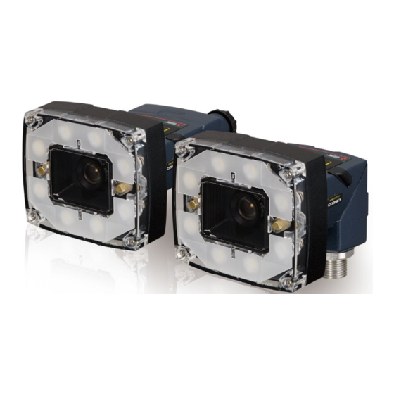
PART NAMES Standard components The three main parts of a vision sensor VS20 are shown below. Item Part name Optics module, featuring high brightness white LED ring light and 8 mm lens Main module, including image sensor and CPU I/O connector module Connectors and indicators The built-in lighting system and other features of a vision sensor VS20 are shown below. - Page 16 Indicator display specifications The display specifications for each indicator are as follows. Item Color Meaning Power indicator Green Power ON Status indicator Yellow Active Pass/Fail indicator Green Pass (default Fail (default Network status indicator Yellow Link up Orange (blink) Data transfer Error indicator Error *1 The status can be changed by setting "Inputs/Outputs"...
-
Page 17: Chapter 3 Specifications
SPECIFICATIONS This chapter shows the specifications of vision sensor VS20s. General Specifications The following shows the general specifications of vision sensor VS20s. Item Specifications Ambient operating temperature 0 to 40 Ambient storage temperature -10 to 60 Maximum humidity Less than 95% RH, non-condensing Vibration resistance IEC 60068-2-6: A vibration of 10 G (10 to 500 Hz at 100 m/... -
Page 18: Performance Specifications
Performance Specifications The following shows the performance specifications of vision sensor VS20s. Specifications VS20M-11F310 VS20M-12F410 VS20C-12F410 VS20M-13F410 VS20C-13F410 Memory 32 MB flash memory Unlimited storage when storing in the remote network device Image processing: 128 MB SDRAM 1/3-inch CMOS, 4.80 mm×3.60 mm (W×H), 3.75 μm sq. pixels Imager type Lens S-mount/M12, 8 mm (standard), Options: 3.6 mm, 6 mm, 12 mm, 16 mm, 25 mm... -
Page 19: Working Distance And Field Of View
Working distance and field of view The distance from a lens to an inspection target is referred to as 'working distance', and an area where a vision sensor can see at that distance is referred to as 'field of view.' As the working distance increases, so does the field of view. -
Page 20: I/O Specifications
I/O Specifications This section shows the connection example of the image acquisition trigger input and high-speed outputs, and specifications for cables and connectors. For details of breakout cables, refer to the following section. Page 22 Breakout cable specifications Image acquisition trigger input An opto-isolated image acquisition trigger input (×1) is integrated into a vision sensor. -
Page 21: High-Speed Outputs
High-speed outputs High-speed outputs can be set as either a sink line or source line. Specifications Description Voltage 28 VDC maximum through external load Current • Sink type or source type: Max. 50 mA • Leakage current in OFF status: 100 μA •... -
Page 22: High-Speed Output Wiring
High-speed output wiring To connect to the inputs of a sink type programmable controller, connect 'High-speed output 0' to 'High-speed output 3' of a breakout cable directly to the input terminals of the controller inputs. When 'High-speed output 0' to 'High-speed output 3' are turned ON, the input terminals are pulled down to 3 V DC or less. High-speed output 0 Output common Sink type programmable controller input... -
Page 23: Ethernet Cable Specifications
Ethernet cable specifications Ethernet cables are used for the network communication by Ethernet connection. By using an Ethernet cable, a vision sensor can directly be connected to a single device, and also can be connected to multiple devices via a switching hub or a router. M12X-code, RJ-45 cable P1: To a vision sensor •... -
Page 24: Breakout Cable Specifications
Breakout cable specifications Breakout cables provide power supply input, image acquisition trigger input, general-purpose input, high-speed output, and RS-232 serial communication. Breakout cables are not terminated. P1: To a vision sensor A: Power supply return pass Pin Number Signal name Wire color High-speed output 2 (Direct 2) Yellow... -
Page 25: I/O Module Cable Specifications
I/O module cable specifications I/O module cables are used for connecting vision sensors to I/O modules directly. When an I/O module is used, all power supplies and communication lines used for vision sensors are connected via a I/O module cable. P1: To a vision sensor Cables are sold separately. -
Page 26: Chapter 4 Function List
FUNCTION LIST The main functions of In-Sight Explorer are listed below. For details, refer to the help of In-Sight Explorer. Function name Description Application Steps The settings, which are necessary to use a vision sensor, are displayed in the order so that the settings can be made easily. - Page 27 Features that can be set with the presence/absence judgment tool for each model : Supported, : Not supported Feature VS20M-11F310 VS20M-12F410 VS20C-12F410 VS20M-13F410 VS20C-13F410 Pattern (gray scale) (color) (gray scale) (color) Pixel counting Brightness ...
-
Page 28: Chapter 5 System Configuration
SYSTEM CONFIGURATION Ethernet Connection The following figure shows the system configuration for Ethernet connection. (3) Engineering tool, Profile (4) Vision sensor setup tool (8) Ethernet cable (2) Programmable controller (8) Ethernet cable (7) Switching (1) Vision sensor 24 VDC power supply (6) Breakout cable (5) Ethernet cable 100 V power supply... -
Page 29: I/O Connection
I/O Connection The following figure shows the system configuration for I/O connection. (3) Engineering tool (4) Vision sensor setup tool (8) Ethernet cable (2) Programmable controller (7) Switching (1) Vision sensor 24 VDC power supply (5) Ethernet cable 100 V power supply (6) Breakout cable (COGNEX product) 5 SYSTEM CONFIGURATION... -
Page 30: I/O Connection Using An I/O Module
I/O Connection Using an I/O Module The following figure shows the system configuration for I/O connection using an I/O module. (3) Engineering tool (4) Vision sensor setup tool (8) Ethernet cable (2) Programmable controller (7) Switching (10) I/O wire (1) Vision sensor 24 VDC power supply (5) Ethernet cable... -
Page 31: Hardware Components
Hardware Components The hardware components of the system configuration are as follows. Component name Remarks Reference Vision sensor Vision sensor VS20 Programmable controller Required for using vision sensors. Page 30 Available CPU modules Engineering tool, profile Required for setting a programmable controller Page 30 Configuration tools Vision sensor setup tool Required for setting a vision sensor... -
Page 32: Applicable System
Applicable System The configuration tools and modules that are available for a vision sensor VS20 are as follows. When using CC-Link IE Field Network Basic or iQ Sensor Solution functions Available CPU modules CPU module Version RnCPU, RnENCPU The firmware version is 28 or later. FX5CPU The firmware version is 1.040 or later. -
Page 33: Hardware Components And Optional Items
Hardware Components and Optional Items Items to prepare This section shows the items required for the system configuration. Cables The cables that are available for a vision sensor VS20 are as follows. Product name Model (COGNEX model) Remarks Ethernet cable CCB-84901-2001-02 Cable length 2 m, M12 connector⇔RJ-45 connector, straight CCB-84901-2001-05... - Page 34 Filter and light cover The filters and light covers that are available for a vision sensor VS20 are as follows. Product name Model (COGNEX model) Remarks Filter and light cover IMPF-2000-POLAR Polarizer IMRF-2000-BP635 Red bandpass filter IMBF-2000-BP470 Blue bandpass filter IMIF-2000-BP850 IR bandpass filter IFS-2000-HBRING-CV...
-
Page 35: Chapter 6 System Construction
SYSTEM CONSTRUCTION This chapter explains how to install standard components and attach accessories to a vision sensor VS20. Installation Environment Before installing a vision sensor, check that the installation environment complies with the precautions for use and general specifications. 2 PRECAUTIONS FOR USE Page 15 General Specifications Change in Sensor Configuration (Straight to Right Angle) - Page 36 Detach the main module and the I/O connector module by pulling them apart. Change the orientation. Make sure that the gasket is properly fixed on the main module. Reattach the I/O connector module to the main module. Attach the washers and fasten the module loosely with two cap nuts. In this case, be careful not to tighten the cap nuts firmly with a T10 torx driver.
- Page 37 When fastening the cap nut, fix it with a torque of 0.12 N⋅m. Then install the screw cover. There are unique left and right screw covers. Take care to attach them correctly. 6 SYSTEM CONSTRUCTION 6.2 Change in Sensor Configuration (Straight to Right Angle)
-
Page 38: Installation Of A Vision Sensor
Installation of a Vision Sensor Installation in straight configuration Use the universal mounting bracket (DM100-UBRK-000) with the mounting holes on the I/O connector module. M3 × 3.5 Installation in right-angle configuration M3 × 3.5 Installing a vision sensor at a slight angle (15°) can reduce reflections of light in target objections. 6 SYSTEM CONSTRUCTION 6.3 Installation of a Vision Sensor... -
Page 39: Connection Of An Ethernet Cable
Connection of an Ethernet Cable This section shows the procedure for connecting an Ethernet cable. Operating procedure Connect the Ethernet cable’s M12 connector to the vision sensor’s Ethernet connector. Connect the Ethernet cable’s RJ-45 connector to the switching hub or personal computer, as applicable. Precautions The cable is designed to connect with its key aligned with the keyway of the connector on the Vision Sensor. -
Page 40: Connection Of A Breakout Cable
Connection of a Breakout Cable This section shows the procedure for connecting a breakout cable. For the specifications on the breakout cable, refer to the following section. Page 22 Breakout cable specifications Operating procedure Verify that the 24 V DC power supply being used is unplugged and not receiving power. Connect an I/O or a serial wire to an appropriate device (such as a programmable controller). -
Page 41: Connection Example Of A Breakout Cable
Connection example of a breakout cable This section shows an example for connecting a breakout cable. Sink type • Input module (positive/negative common shared type) • Output module (sink type) Trigger (Orange) General-purpose input 0 (Violet) High-speed output 0 (Blue) High-speed output 1 (Grey) High-speed output 2 (Yellow) Breakout cable... -
Page 42: Focus Position Setting
Focus Position Setting Focus can be adjusted using the screw on the back of a light module. Turn the screw clockwise for the shorter focal length, and counterclockwise for the longer focal length. Start the vision sensor setup tool and set up the focus while checking the effect. -
Page 43: Lens Replacement
Lens Replacement Operating procedure Verify that the 24 V DC power supply being used is unplugged and not receiving power. Remove the four screws and the front cover from the optics module. Move the lens to the furthest out position by turning the screw on the back of the light module clockwise. 6 SYSTEM CONSTRUCTION 6.7 Lens Replacement... - Page 44 Turn the lens counterclockwise with your fingers to remove the lens. Insert the new lens and using your fingers, turn it clockwise to tighten the lens. Reattach the front cover. Tighten four screws with a torque wrench. The maximum tightening torque is 0.20 N⋅m. Turn ON the 24 V DC power supply.
-
Page 45: Installation Of A Lens Filter
Installation of a Lens Filter This section shows the procedure for installing a lens filter. Operating procedure Verify that the 24 V DC power supply being used is unplugged and not receiving power. Remove the four screws and the front cover from the optics module. Unscrew the two screws on the filter holder and remove the filter holder from the front cover. - Page 46 Reinstall the filter holder back to the front cover, tightening the two screws until they stop turning. Reattach the front cover. Tighten four screws with a torque wrench. The maximum tightening torque is 0.20 N⋅m. Turn ON the 24 V DC power supply. 6 SYSTEM CONSTRUCTION 6.8 Installation of a Lens Filter...
-
Page 47: Replacement Of An Led Ring Light
Replacement of an LED Ring Light Operating procedure Verify that the 24 V DC power supply being used is unplugged and not receiving power. Remove the four screws and the front cover from the optics module. Using a screwdriver, loosen the two screws on the LED ring light. 6 SYSTEM CONSTRUCTION 6.9 Replacement of an LED Ring Light... - Page 48 Remove the LED ring light. Carefully align the connector on the back of the new LED ring light with the pins on the vision sensor. Gently press down the LED ring light to the optics module. Using a screwdriver, tighten the screws until they stop turning. Reattach the front cover.
-
Page 49: Connection Of An I/O Module
6.10 Connection of an I/O Module This section shows the specifications and procedure for connecting an I/O module. Specifications of CIO-1400 I/O modules For the connection between an I/O module and a programmable controller, use a terminal block or an RS232 OUT port. (1) (2) Connector/Indicator Description... -
Page 50: Connection Procedure Of A Cio-1400 I/O Module
Connection procedure of a CIO-1400 I/O module This section shows the procedure for connecting a CIO-1400 I/O module. Operating procedure Page 48 Connecting an I/O module to a power supply Page 48 Connecting an I/O module to a frame ground Page 49 Connecting an I/O module (terminal block) to an input/output module Page 49 Connecting an I/O module (RS232 OUT port) to a serial communication module Page 49 Connecting an I/O module cable to a vision sensor... - Page 51 Connecting an I/O module (terminal block) to an input/output module Operating procedure Decide how to connect the terminal block of the I/O module to the device. Using a screwdriver, loosen the applicable screw terminals. Connect I/O wires to I/O terminals of the terminal block. Connect the other end of the cable to the relevant I/O device.
-
Page 52: Connection Example Of A Cio-1400 I/O Module
Connection example of a CIO-1400 I/O module This section shows an example for connecting a CIO-1400 I/O module. Sink type • Input module (positive/negative common shared type) • Output module (sink type) 24 VDC Trigger 24 VDC General-purpose input 1 Input common General-purpose output 3 General-purpose output 2... -
Page 53: Chapter 7 Installation
For details on how to register profiles, refer to the following manuals. GX Works2 Version 1 Operating Manual (Common) GX Works3 Operating Manual For information on how to obtain a profile, please contact your local Mitsubishi Electric sales office or representative. 7 INSTALLATION 7.1 Software Installation... - Page 54 MEMO 7 INSTALLATION 7.2 Registration of a Profile...
-
Page 55: Chapter 8 Maintenance And Inspection
MAINTENANCE AND INSPECTION Cleaning a Vision Sensor Housing • To clean the outside of the vision sensor housing, apply a small amount of mild detergent cleaner or isopropyl alcohol on a cleaning cloth. • Do not attempt to clean the vision sensor with harsh or corrosive solvents, including lye, methyl ethyl ketone (MEK) or gasoline. - Page 56 MEMO 8 MAINTENANCE AND INSPECTION 8.3 Cleaning a Lens Cover...
-
Page 57: Chapter 9 Troubleshooting
TROUBLESHOOTING If an error occurred while using a vision sensor, check the troubleshooting in the help of In-Sight Explorer and take corrective action. 9 TROUBLESHOOTING... - Page 58 MEMO 9 TROUBLESHOOTING...
-
Page 59: Appendix
APPENDIX Appendix 1 External Dimensions The following figures show the size of a vision sensor in the straight configuration. 22.3mm 52.2mm 19.9mm 42.4mm 75.2mm 60.4mm 88.2mm 57.9mm 32.0mm 37.0mm The following figures show the size of a vision sensor in the right angle configuration. 65.0mm 52.2mm 36.4mm... - Page 60 MEMO APPX Appendix 1 External Dimensions...
- Page 61 MEMO APPX Appendix 1 External Dimensions...
-
Page 62: Revisions
Japanese manual number: SH-081768-D This manual confers no industrial property rights of any other kind, nor does it confer any patent licenses. Mitsubishi Electric Corporation cannot be held responsible for any problems involving industrial property rights which may occur as a result of using the contents noted in this manual. -
Page 63: Warranty
WARRANTY Please confirm the following product warranty details before using this product. 1. Gratis Warranty Term and Gratis Warranty Range If any faults or defects (hereinafter "Failure") found to be the responsibility of Mitsubishi occurs during use of the product within the gratis warranty term, the product shall be repaired at no cost via the sales representative or Mitsubishi Service Company. -
Page 64: Trademarks
TRADEMARKS The following are registered trademarks of Cognex Corporation: Cognex, 2DMAX, Advantage, AlignPlus, Assemblyplus, Check it with Checker, Checker, Cognex Vision for Industry, Cognex VSOC, CVL, DataMan, DisplayInspect, DVT, EasyBuilder, Hotbars, IDMax, In-Sight, Laser Killer, MVS-8000, OmniView, PatFind, PatFlex, PatInspect, PatMax, PatQuick, SensorView, SmartView, SmartAdvisor, SmartLearn, UltraLight, Vision Solutions, VisionPro, VisionView The following are trademarks of Cognex Corporation: The Cognex logo, 1DMax, 3D-Locate, 3DMax, BGAII, CheckPoint, Cognex VSoC, CVC-1000, FFD, iLearn, In-Sight (design... - Page 66 Cognex Corporation www.cognex.com SH(NA)-081769ENG-D(1903)KWIX MODEL: VS20M/C-U-E MODEL CODE: 13JX76 HEAD OFFICE : TOKYO BUILDING, 2-7-3 MARUNOUCHI, CHIYODA-KU, TOKYO 100-8310, JAPAN NAGOYA WORKS : 1-14 , YADA-MINAMI 5-CHOME , HIGASHI-KU, NAGOYA , JAPAN When exported from Japan, this manual does not require application to the Ministry of Economy, Trade and Industry for service transaction permission.
Need help?
Do you have a question about the MELSENSOR Vision Sensor VS20 Series and is the answer not in the manual?
Questions and answers