Table of Contents
Advertisement
Quick Links
Scopo del manuale
Questo manuale è stato redatto dal costruttore ed è parte integrante del prodotto.
Le informazioni in esso contenute sono direttte agli operatori esperti che eseguono l' installazione e la manutenzione straordinaria.
Essi devono possedere competenze specifiche e particolari capacità per eseguire correttamente ed in sicurezza gli interventi di loro competenza. La costante osservanza
delle informazioni garantisce la sicurezza dell'uomo, l'economia di esercizio ed una piú lunga durata di funzionamento del prodotto. Al fine di evitare manovre errate con
il rischio di incidenti, è importante leggere attentamente questo manuale, rispettando scrupolosamente le informazioni fornite. Considerando che tale prodotto va installato
in abitazioni residenziali, l'operatore esperto, dopo aver effettuato l'intervento dovrá constatarne la corretta installazione ed il regolare funzionamento. Successivamente
dovrá istruire l'utente sull'uso corretto del prodotto rilasciando tutta la documentazione prevista dal costruttore.
L'indice descrittivo, posto all'inizio, consente facilmente la rintracciabilitá degli argomenti di interesse.
Purpose of the manual
This manual was drawn up by the manufacturer and is an integral part of the product.
The information it contains is addressed to expert operators that carry out the installation and maintenance operations.
They must have the specific qualifications and training to carry out this work correctly and under the maximum safety conditions.
Strict observance of the instructions contained in the manual will ensure safety, optimum operation and prolonged functioning of the product. To avoid incorrect
manoeuvres and therefore the risk of accidents, it is essential to read this manual with care and strictly follow all the instructions given. As this is a product to be installed
in residential buildings, the expert installer, after completing installation must verify that this has been performed correctly and that the product functions smoothly.
Subsequently, it is necessary to instruct the user on the correct use of the product providing all the documentation envisaged by the manufacturer.
The table of contents, at the beginning, makes it easy to find the topics of interest.
Objectif de la notice
Cette notice a été rédigée par le fabricant et fait partie intégrante du produit.
Les informations qui y sont contenues s'adressent aux opérateurs spécialisés qui effectuent les opérations d'installation et d'entretien extraordinaire.
Ceux-ci doivent posséder les compétences et les qualités requises pour effectuer de façon correcte et en toute sécurité les interventions dont ils sont chargés. La constante
observation de ces informations garantit la sécurité des personnes, une économie d'utilisation et une plus longue durée de vie du produit. Lire attentivement cette notice
et en respecter scrupuleusement les informations pour éviter toute fausse manoeuvre qui pourrait entraîner des accidents. Ce produit étant destiné aux habitations
résidentielles, après en avoir effectué la pose, l'opérateur devra en vérifier la bonne installation et le bon fonctionnement .
Il devra ensuite informer l'utilisateur de l'emploi correct du produit et lui remettre toute la documentation prévue par le fabricant.
Le sommaire détaillé, placé au début de la notice, permet de retrouver facilement les sujets à consulter.
Zweck der Montageanleitung
Das vorliegende Handbuch wurde vom Hersteller verfaßt und ist Bestandteil des Produkts.
Die darin enthaltenen Informationen richten sich an erfahrenes Personal, das sowohl die Installation als auch außerordentliche Wartungsarbeiten durchführt.
Dieses Personal muß über spezifische Fähigkeiten und Kompetenzen verfügen, um die Arbeit korrekt und unter sicheren Bedingungen durchführen zu können.
Die ständige Beachtung der Anweisungen gewährleistet Sicherheit, wirtchaftlichen Betrieb der Anlage und eine längere Lebensdauer des Produkts.
Zur Vermeidung von Fehlern, die zu Unfällen führen könnten, muß das vorliegende Handbuch aufmerksam durchgelesen und die darin enthaltenen Anweisungen genau
befolgt werden.
Da das Produkt im Privatwohnbereich installiert wird, muß das erfahrene Personal nach der Installation die korrekte Montage und den einwandfreien Betrieb überprüfen.
Anschließend muß es den Benutzer in den richtigen Gebrauch des Produkts einweisen und ihm die vom Hersteller vorgesehene Dokumentation aushändigen.
Das Inhaltsverzeichnis am Anfang des Handbuchs ermöglicht eine schnelle Ermittlung der jeweiligen Punkte.
Objetivo del manual
Este manual ha sido redactado por el constructor y forma parte integrante del producto. Las informaciones que contiene van dirigidas a los operadores especializados
encargados de las operaciones de instalación y mantenimiento extraordinario.
Dichos operadores deberán poseer la competencia especifica y las capacidades necesarias para llevar a efecto correctamente y en condiciones de seguridad las
operaciones de las que están encargados.
El cumplimiento constante de estas instrucciones garantiza seguridad del personal, economía de uso y un funcionamento más duradero del producto. A fin de evitar
maniobras incorrectas con el consiguiente riesgo de accidentes cabe leer con atención este manual y respetar escrupulosamente las instrucciones.
Puesto que el producto está destinado a la instalación en viviendas, el operador especializado, después de realizar la instalación, deberá comprobar la correcta ejecución
de la misma y el buen funciomento del producto.
También deberá enseñar al cliente cómo utilizar correctamente el producto, entregando toda la documentación facilitada por el constructor.
El índice descriptivo inicial permite encontrar con facilidad los temas que interesen.
ZT 71
ZT 72
SISTEMA OLEODINAMICO
CANCELLI AD ANTA
BATTENTE CON
OPERATORE
OLEODINAMICO
INTRERRATO
Istruzioni per l'installazione
HYDRAULIC SYSTEM FOR
SWING-GATES WITH PUMP
UNIT AND UNDERGROUND
HYDRAULIC JACK
Installation instructions
SYSTEME
OLEODYNAMIQUE POUR
PORTAILS A VANTAIL
BATTANT AVEC
OPERATEUR
OLEODYNAMIQUE
ENTERRE
Instructions d'installation
ELEKTROHYDRAULISCHER
UNTERFLURDREHTORANTRIEB
Montageanleitung
SISTEMA OLEODINAMICO
PARA CANCELAS DE
PUERTA BATIENTE CON
OPERADOR
OLEODINAMICO
ENTERRADO
Instrucciones de instalación
PER UN CORRETTO MONTAGGIO LEGGERE ATTENTAMENTE LE ISTRUZIONI.
FOR A CORRECT ASSEMBLY, CAREFULLY READ THE FOLLOWING.
POUR UN ASSEMBLAGE CORRECT, LIRE ATTENTIVEMENT LES ISTRUCTIONS.
FÜR EINE KORREKTE INSTALLATION, DIESE ANLEITUNGEN SORGFÄLTING LESEN.
LEER ATENTAMENTE LAS INSTRUCCIONES PARA UN MONTAJE CORRECTO.
Advertisement
Table of Contents

Related Manuals for Aprimatic ZT 71


Summary of Contents for Aprimatic ZT 71
- Page 1 ZT 71 ZT 72 SISTEMA OLEODINAMICO CANCELLI AD ANTA BATTENTE CON OPERATORE OLEODINAMICO INTRERRATO Scopo del manuale Istruzioni per l'installazione Questo manuale è stato redatto dal costruttore ed è parte integrante del prodotto. Le informazioni in esso contenute sono direttte agli operatori esperti che eseguono l’ installazione e la manutenzione straordinaria.
-
Page 2: Table Of Contents
Dimensions du groupe actionneur hydraulique souterrain ZT 71 -ZT 72 Abmessungen des unterirdischen öldynamischen Antriebskomplexes ZT 71 – ZT 72 Dimensiones del grupo operador hidráulico enterrado ZT 71 - ZT 72 ..........................pag. Specifica delle versioni dell’interrato ZT 71 - ZT 72 Specifications of the ZT 71 - ZT 72 underground versions Spécifications des version du souterrain ZT 71 - ZT 72... - Page 3 Installation of the ZT 71 (110°) ZT 72 (220°) operator Installation de l’actionneur ZT 71 (110°) ZT 72 (220°) Installation des Triebs ZT 71 (110°) ZT 72 (220°) Instalacón del operador ZT 71 (110°) ZT 72 (220°) ................................pag. Istruzioni per lo sfiato dell’apparecchiatura Instructions to bleed the appliance Instructions pour la purge du dispositif Anleitung für die Entlüftung des Geräts...
-
Page 4: Dati Tecnici
TECHNICAL DATA CARACTERISTIQUES TECHNIQUES TECHISCHE DATEN DATOS TECNICOS DATI TECNICI / TECHNICAL DATA DETAILS TECHNIQUES / TECHNISCHE DATEN DATOS TECNICOS ZT 71 ZT 72 ZT 71 ZT 72 potenza assorbita (W) portata pompa (lt./min.) Absorbed power (W) Pump capacity (l/min) puissance absorbée (W) -
Page 5: Caracteristiques Generales
Las diferentes versiones de bloqueo y caudal se ilustran en el cuadro de los datos técnicos. DIMENSIONI DEL COMPLESSO OPERATORE OLEODINAMICO INTERRATO ZT 71 - ZT 72 DIMENSIONS OF THE ZT 71 - ZT 72 UNDERGROUND HYDRAULIC OPERATOR GROUP DIMENSIONS DU GROUPE ACTIONNEUR HYDRAULIQUE SOUTERRAIN ZT 71 -ZT 72 ABMESSUNGEN DES UNTERIRDISCHEN ÖLDYNAMISCHEN ANTRIEBSKOMPLEXES ZT 71 –... -
Page 6: Specifica Delle Versioni Dell'interrato Zt 71 -Zt 72
(vedi paragrafo CONTROLLI PRELIMINARI e VERIFICA SCELTA AUTOMAZIONE). SPECIFICATIONS OF THE ZT 71 - ZT 72 UNDERGROUND VERSIONS Model with double hydraulic lock on opening and closing. The use of this version depends on the weight of the gate and its length. It is produced in two versions: B4 .. -
Page 7: Controlli Preliminari
CONTROLLI PRELIMINARI Prima di eseguire il lavoro di installazione occorre verificare le condizioni del cancello da automatizzare: La costruzione meccanica deve essere robusta e rigida. Le cerniere non devono avere giochi o forti attriti e devono essere adeguate al peso dell'anta. Verificare che l'anta sia perfettamente a piombo. -
Page 8: Disposizione Dei Componenti (B2)
C - Manual key control (magnetic, digital, key-pad, mechanical, etc.) D - Aprimatic microprocessor control unit in sealed box (position, were possible, so that it is protected against the atmospheric agents) ( see price list) E - Aprimatic remote control receiver (can be fitted inside the flashing lamp) (model RG/RR) F - Tube for hydraulic control unit power supply cable coming from the control unit. -
Page 9: Anordnung Der Bauteile (B2)
C - Dispositivo de mando manual a llave ( magnética, digital, combinador de teclado, mecánica, etc.) D - Cuadro de maniobras Aprimatic con microprocesador en caja estanca (colocar, si es posible el cuadro fuera del alcance de los agentes externos) (véaselista) E - Radio receptor mando a distancia Aprimatic (posibilidad de inserción en el destellador) (modelo RG/RR - véase lista) -
Page 10: Verifica Componenti
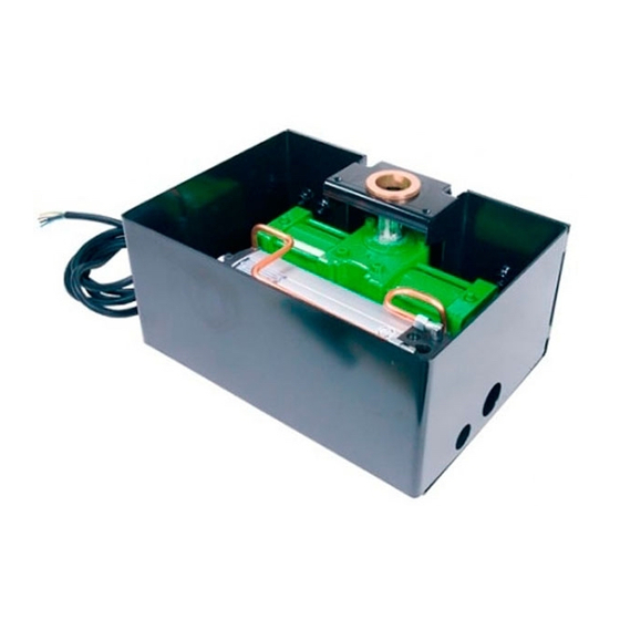
Viti TE 10x25 + dadi ES.M10 Qt.2 Dima per messa in fase martinetto Qt.1 * Venduta separatamente - Vedere listino LiST OF THE ZT 71 - ZT 72 OPERATOR COMPONENTS * CIA 171 BOX (B5) CONTROL UNIT - CYLINDER (B4) Pos. Description Box cover 1 pc. -
Page 11: Verzeichnis Der Komponenten Trieb Zt 71 - Zt 72
VERZEICHNIS DER KOMPONENTEN TRIEB ZT 71 - ZT 72 * KASTEN CIA 171 (B5) STEUEREINHEIT - ZYLINDER (B4) Pos. Bezeichnung Pos. Bezeichnung Kastendeckel 1.St Steuereinheit ZT 70 1.St Plastikvershlüssel 2.St Zylinder ZT 71 - ZT 72 1.St Sechskantschrauben 6x14 + Scheiben 2.St... -
Page 12: Preparazione Al Montaggio
ATTREZZATURA BASE E MATERIALE DI CONSUMO OCCORRENTE Livella a bolla (tridimensionale) Occhiali di protezione Grasso tipo grafitato. Maschera di protezione Olio tipo AprimOil HC 13 (olio espressamente formulato per Aprimatic) Saldatore da stagno Bomboletta Zincospray Trapano elettrico di potenza adeguata alimentazione 220 V. Vernice antiruggine... -
Page 13: Vorbereitung Zur Montage
Elektrische Bohrmaschine mit angemessener Leistung, Versorgung: Graphitiertes Schmierfett 220 V Öl Typ AprimOil HC 13 Bohrer (speziell für Aprimatic entwickeltes Öl) Topffräser Ø 67 für Aufnahmebohrungen Lichtschranken und Bedientafeln Sprayflasche “Zincospray” Verlängerungskabel für elektrische Ausrüstung Rostschutzlack Elektrokabel Schnitt 1,5 mm... -
Page 14: Cassetta Di Fondazione Cia 171
CASSETTA DI FONDAZIONE CIA 171 Le casse di fondazione permettono di predisporre il cancello ad una successiva installazione dell’operatore oleodinamico ZT71 - ZT72. Le modalità di posizionamento della cassetta sono le seguenti: - Controllare che tra l’asse di rotazione dell’anta ed il pilastro (o muro di sostegno) vi siano almeno 60 mm (C 1). -
Page 15: Installazione Cassetta Di Fondazione Cia 171
INSTALLAZIONE CASSETTA DI FONDAZIONE CIA 171 - Posizionare la cassetta all’interno dello scavo. - Inserire, negli appositi fori predisposti sulla cassetta, i condotti per il drenaggio dell’acqua (C3 (1) e quelli per il passaggio dei tubi idraulici di alimentazione dell’operatore (C3 (2)). - Inserire la bussola (C3 (3)) nella bronzina, quindi posizionare definitivamente la cassetta in modo tale che l’asse della bussola sia perfettamente allineato e centrato con l’asse delle cerniere del cancello. -
Page 16: Posizionamento Della Bussola
POSIZIONAMENTO DELLA BUSSOLA - Posizionare la dima sulla cassetta allineando l’asse della tacca centrale A con l’asse della tacca incisa sulla cassetta (C5) in base al tipo di operatore scelto (utilizzare la dima riportata nell’ultima pagina delle istruzioni cassetta CIA 171): ZT71 (110°) Portare l’asse del foro della bussola allineato con la tacca centrale A della dima. - Page 17 - Inserire l’operatore all’interno della cassetta, quindi completare il montaggio secondo le modalità indicate precedentemente relative all’installazione dell’ ZT71. INSTALLATION OF THE ZT 71(110°) ZT 72 (220°) OPERATOR To install the hydraulic operator, proceed as follows: - Open the gate half way.
-
Page 18: Installation Des Triebs Zt 71 (110°) Zt 72 (220°)
INSTALLATION DES TRIEBS ZT 71 (110°) ZT 72 (220°) Zur Installation des Hydraulikantriebs wie folgt vorgehen: - Den Torflügel ungefähr um die Hälfte des gesamten Laufweges öffnen. - Den Deckel des Kastens abnehmen. - Prüfen, ob die Markierung auf dem Kopf der Keilwelle des Antriebs mit jener auf dem Gehäuse des Antriebs übereinstimmt (siehe Ausschnitt C6(1)). - Page 19 ISTRUZIONI PER LO SFIATO DELLA CENTRALINA IDRAULICA Lo sfiato é già eseguito in produzione, non é necessario ripetere l’operazione. AVVERTENZA Nel caso di sostituzione del martinetto, o della centralina idraulica, eseguire a banco lo sfiato aria prima di reinstallare l’operatore (C9) INSTRUCTIONS TO BLEED THE HYDRAULIC CONTROL UNIT Bleeding is factory-done during production.
-
Page 20: Allacciamento Elettrico
ALLACCIAMENTO ELETTRICO Collegare il cavo che esce dalla centralina idraulica al cavo di collegamento della apparecchiatura elettrica tramite una morsettiera (D1 ) non fornita nell'imballo. AVVERTENZA Il cavo di corredo della centralina è a quattro fili così distinguibili: Celeste ......comune motore Nero ...... -
Page 21: Conexion Electrica
CONEXION ELECTRICA Conectar el cable que sale de la centralita hidráulica con el cable de conexión del equipo electronico por medio de una regleta de bornes (D1 ) no suministrada. ADVERTENCIA El cable de la centralita consta de cuatro hilos: Azul ...... - Page 22 If wing movement requires too high a pressure, the mechanics, the perpendicular hanging and the friction of the door should be carefully examined. • Once the adjustments have been made, close the CIA 171 box housing the ZT 71- ZT 72 operator with the special cover (D5 ).
-
Page 23: Einstellung Von Druck Und Schubkraft
REGOLAZIONE FRENATA IN FASE DI APERTURA E CHIUSURA (D5 ). Después de haber efectuado todas las regulaciones, cierre la caja CIA 171 que aloja el operador ZT 71- ZT 72 con su tapadera La regolazione dell'ammortizzazione della frenata nella fase finale di rotazione del cancello si esegue... -
Page 24: Einstellung Der Abbremsung Bei Öffnungs-Und Schliessbewegung
REGLAGE DU FREINAGE LORS DE L’OUVERTUREET DE LA FERMETURE Once installation has been completed it is necessary to fit the gate with the appropriate sign- board (D 7(3)) Le réglage de l’amortissement du freinage en fin de cycle de rotation du portail s’effectue par l’intermédiaire de deux soupapes (D6 ) situées sur le vérin:en dévissant les soupapes on obtient un ralentissement progressif du vantail, en les vissant on obtient un ralentissement brusque;... -
Page 25: Montage Desaxe Du Verin
MONTAGE DESAXE DU VERIN Lorsqu’il n’est pas possible de monter le vérin sur le même axe que les gonds du vantail, dans le cas de portails avec de nombreuses charnières, d’un poids supérieur au poids maximum autorisé, ou bien comme variante au cas précédent, on peut faire recours au montage désaxé du vérin. Dans ce cas, le mouvement est transmis au vantail par un bras télescopique fourni comme accessoire en option (voir tarif). -
Page 26: Guida Ricerca Guasti
Fuoriuscita di olio dal foro della vite di sfiato. Smontare il martinetto ed inviarlo Perdite di olio dalle flange laterali del Forzatura del cancello per ad un centro assistenza Aprimatic martinetto. effrazione o per conseguenza di un per la riparazione. -
Page 27: Trouble-Shooting
Dismantle the jack and send it to an Oil leak from the lateral flange of the jack. Forcing of the gate due to burglars or due to jerky functioning. Aprimatic service centre for repair. The gate is not perfectly perpendicular. Plumb the gate. -
Page 28: En Cas De Pannes
Dismantle the jack and send it to an Fuites d’huile des flasques latéraux du vérin. Forcing of the gate due to burglars or due to jerky functioning. Aprimatic service centre for repair. Plumb the gate. The gate is not perfectly perpendicular. -
Page 29: Fehlersuche
Überschüssiges Öl aus dem Hydrauli- kaggregat entfernen Drehzylinder abbauen und einer Tor ist manuell forciert worden aufgrund von Ölverlust aus dem Seitenflanschen des Kundendienststelle von Aprimatic Einbruch oder in Folge eines ruckweisen Betriebs Drehzylinders zwecks Reparatur zuschicken. Torflügel nicht im Lot. -
Page 30: Guia De Averias
Pérdidas de aceite de las bridas laterales del Desmontar el gato y enviarlo a un consecuencia de un funcionamiento por golpes. gato. centro de Asistencia Aprimatic para su reparación. La puerta no está a plomo. La cancela se mueve de manera intermitente. -
Page 31: Istruzioni Per L'utilizzatore
ISTRUZIONI PER L’UTILIZZATORE Per sbloccare l’apparecchiatura aprire la valvola di sblocco posta sulla centralina. L’operazione é fattibile grazie alla chiavetta triangolare in dotazione che dovrà essere ruotata in senso antiorario. Per bloccarla invece basterà chiudere la valvola di sblocco ruotando la chiavetta triangolare in senso orario come in fig.E1 END USER INSTRUCTION To release the appliance, open the unlock valve located on the control unit. - Page 32 Aprimatic S.p.A. - Via Galileo Galilei 67 - Z.I. Fossatone - 40060 Villa Fontana di Medicina - Bologna - Italy Tel. (39) 51 6979800 - Fax (39) 51 6930390...
Need help?
Do you have a question about the ZT 71 and is the answer not in the manual?
Questions and answers