Table of Contents
Advertisement
Available languages
Available languages
SCOPO DEL MANUALE
Questo manuale è stato redatto dal costruttore ed è parte integrante del prodotto.
In esso sono contenute tutte le informazioni necessarie per:
• la corretta sensibilizzazione degli installatori alle problematiche della sicurezza;
• la corretta installazione del dispositivo;
• la conoscenza approfondita del suo funzionamento e dei suoi limiti;
• il corretto uso in condizioni di sicurezza;
La costante osservanza delle indicazioni fornite in questo manuale, garantisce la sicurezza dell'uomo, l'economia di
esercizio e una più lunga durata di funzionamento del prodotto.
Al fi ne di evitare manovre errate con il rischio di incidenti, è importante leggere attentamente questo manuale,
rispettando scrupolosamente le informazioni fornite.
Tutti i dati sono stati redatti e controllati con la massima cura, ma non possiamo accettare responsabilità per eventuali
errori od omissioni. Ci riserviamo di apportare quelle modifi che che sono connesse ai progressi tecnologici.
Garanzia: Le condizioni di garanzia sono da verifi care sul listino vendite in base agli accordi commerciali.
Le istruzioni, i disegni, le fotografi e e la documentazione contenuti nel presente manuale sono di proprietà
APRIMATIC S.p.a. e non possono essere riprodotti in alcun modo, né integralmente, né parzialmente.
Il logo "APRIMATIC" è un marchio registrato di APRIMATIC S.p.a.
PURPOSE OF THE MANUAL
This manual was drawn up by the manufacturer and is an integral part of the product.
It contains all the necessary information:
• to draw the attention of the installers to safety related problems
• to install the device properly
• to understand how it works and its limits
• to use the device under safe conditions
Strict observance of the instructions in this manual guarantees safe conditions as well as efficient operation and a
long life for the product.
To prevent operations that may result in accidents, read this manual and strictly obey the instructions provided.
All the specifications have been written and verified with our best attention. We do not undertake responsability for
possible errors or omissions. We reserve the right to introduce changes relative to technological progress.
Guarantee: The guarantee conditions can be checked in the price list on the basis of the commercial agreements.
Instructions, drawings, photos and literature contained herein are the exclusive property of the manufacturer and
may not be reproduced by any means.
The "Aprimatic" logo is a trademark registered by Aprimatic S.p.A.
BUT DU MANUEL
Ce manuel a été rédigé par le constructeur et fait partie intégrante du produit.
Il contient toutes les informations nécessaires pour :
• sensibiliser les installateurs aux problèmes liés à la sécurité ;
• installer le dispositif de manière correcte ;
• connaître le fonctionnement et les limites du dispositif ;
• utiliser correctement le dispositif dans des conditions de sécurité optimales ;
Le respect des indications fournies dans ce manuel garantit la sécurité personnelle, une économie de fonctionnement
et une longue durée de vie du produit.
Afi n d'éviter des opérations incorrectes et de ne pas risquer des accidents sérieux, lire attentivement ce manuel et
respecter scrupuleusement les informations fournies.
Toutes les données ont été rédigées et contrôlées avec le plus grand soin. Nous n'assumons aucune responsabilité
en cas d'erreurs éventuelles ou d'omissions. Nous nous réservons le droit d'apporter des modifi cations concernant
le progrès technologique.
Conditions de garantie: Vérifi ez les conditions de garantie dans le catalogue des ventes sur la base des accords commerciaux.
Les instructions, les dessins, les photos et la documentation contenus dans ce manuel sont la propriété d'APRIMATIC
S.p.A. et ne peuvent être reproduits sous aucune forme, ni intégralement, ni partiellement.
Le logo « Aprimatic » est une marque déposée par Aprimatic S.p.A.
ZWECK DES HANDBUCHS
Dieses Handbuch wurde vom Hersteller verfasst und ist ein ergänzender Bestandteil des Produkts.
Es enthält alle nötigen Informationen für:
• die Sensibilisierung der Monteure für Fragen der Sicherheit;
• die vorschriftsmäßige Installation der Vorrichtung;
• die umfassende Kenntnis ihrer Funktionsweise und ihrer Grenzen;
• die vorschriftsmäßige und sichere Benutzung.
Die Beachtung der in diesem Handbuch enthaltenen Anweisungen gewährleistet die Sicherheit der Personen, den
wirtschaftlichen Betrieb und eine lange Lebensdauer des Produkts.
Zur Vermeidung von Fehlbedienung und somit Unfallgefahr dieses Handbuch aufmerksam durchlesen und die
Anweisungen genau befolgen.
Alle Daten wurden sorgflältigst ausgearbeitet und überprüft. Für eventuelle Fehler oder Auslassungen übernehmen
wir keine Verantwortung. Wir behalten uns vor, solche Änderungen vorzunehmen, welche mit der techologischen
Entwicklung im Zusammenhang stehen.
Garantie: Die Garantiebedingungen sind der Verkaufspreisliste aufgrund der getroffenen Vereinbarungen zu entnehmen.
Die Anleitungen, Zeichnungen, Fotos und Dokumentationen in diesem Handbuch sind Eigentum von APRIMATIC
S.p.A. und dürfen in keiner Weise ganz oder teilweise reproduziert werden.
Das Logo „Aprimatic" ist ein eingetragenes Warenzeichen der Aprimatic S. p. A.
OBJETO DEL MANUAL
Este manual ha sido redactado por el constructor y forma parte integrante del producto.
El mismo contiene todas las informaciones necesarias para:
• la correcta sensibilización de los instaladores hacia los problemas de la seguridad
• la correcta instalación del dispositivo
• el conocimiento en profundidad de su funcionamiento y de sus límites
• el correcto uso en condiciones de seguridad
La constante observación de las indicaciones suministradas en este manual, garantiza la seguridad del hombre, la
economía del ejercicio y una mayor duración de funcionamiento del producto.
Con el fi n de evitar maniobras equivocadas con riesgo de accidente, es importante leer atentamente este manual,
respetando escrupulosamente las informaciones suministradas.
Todos los datos han sido redactados y comprobados con la máxima atención. No asumimos ninguna responsabilidad en
caso de errores posibles u omisiones. Nos reservamos el derecho de hacer modifi caciones relativas al progreso tecnológico.
Garantía: Las condiciones de garantía se deben comprobar en la lista de ventas según los acuerdos comerciales estipulados.
Las instrucciones, los dibujos, las fotografías y la documentación que contiene este manual son propiedad de
APRIMATIC S.p.a. y no pueden ser reproducidas en ninguna manera, ni integral ni parcialmente.
El logotipo "Aprimatic" es una marca registrada de Aprimatic S. p. A.
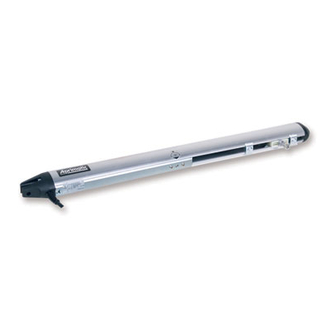
RAIDER 2000
Attuatore elettromeccanico a 24V per cancelli battenti
24V Electro-mechanical operator for swing gates
Opérateur électromécanique à 24 V pour portails battants
24 V Elektromechanischer Antrieb für Drehfl ügeltore
Actuador electromecánico para cancelas batientes
Istruzioni di installazione meccanica, Utilizzo
Mechanical installation, Use and Mainte-
Notice d'installation mécanique, d'Utilisation
Anleitung für die mechanische Installation,
Instrucciones para la instalación mecánica,
el uso y el mantenimiento
e Manutenzione
nance instructions
et d'Entretien
Gebrauch und Wartung
Advertisement
Chapters
Table of Contents

Related Manuals for Aprimatic RAIDER 2000


Summary of Contents for Aprimatic RAIDER 2000
- Page 1 Conditions de garantie: Vérifi ez les conditions de garantie dans le catalogue des ventes sur la base des accords commerciaux. Les instructions, les dessins, les photos et la documentation contenus dans ce manuel sont la propriété d’APRIMATIC S.p.A. et ne peuvent être reproduits sous aucune forme, ni intégralement, ni partiellement.
-
Page 2: Table Of Contents
CANCELLI BATTENTI RAIDER 2000 Terminologia e simboli adottati nel manuale Norme di sicurezza e Obblighi dell’installatore Avvertenze per l’utilizzatore 1. Descrizione dell’attuatore Uso previsto e Campo d’impiego ....................... 4 Caratteristiche generali ..........................4 Dimensioni di ingombro ..........................4 Dati tecnici ..............................4 Componenti di installazione ........................ -
Page 3: Norme Di Sicurezza E Obblighi Dell'installatore
CANCELLI BATTENTI RAIDER 2000 NORME DI SICUREZZA E OBBLIGHI DELL’INSTALLATORE Per lavorare nel pieno rispetto delle norme di sicurezza occorre: • indossare indumenti di protezione a norma di legge (scarpe antinfortunistiche, occhiali di protezione, guanti ed elmetto); • non indossare articoli di abbigliamento che possano impigliarsi (cravatte, bracciali, collane, ecc.). -
Page 4: Descrizione Dell'attuatore
Il prodotto deve essere installato solo con accessori APRIMATIC. Caratteristiche generali - L’operatore Raider 2000 è irreversibile e quindi garantisce il mantenimento delle posizioni di chiusura e di apertura per ante di lunghezza fi no a 1,8 m senza necessità di installare un’elettroserratura. -
Page 5: Componenti Di Installazione
(con riferimento alla Fig.2). rif. descrizione q.tà Attuatore Raider 2000 Apparecchiatura di controllo Aprimatic RSK-24 Coppia fotocellule ER4 N Trasmittente bicanale TR2 Pulsante a chiave PC12 E Lampeggiante ET2 N... -
Page 6: Preparazione All'installazione
Collegamento attuatore/apparecchiatura - poiché l’attuatore è dotato di encoder si raccomanda l’utilizzo del cavo schermato disponibile a catalogo Aprimatic (cavo addizionale schermato a 6 poli, lunghezza 10 m). I dispositivi accessori di controllo e comando e il pulsante di emergenza devono essere collocati entro il campo visivo dell’automazione, lontano da parti in movimento e a un’altezza minima da terra di 1,5m. -
Page 7: Verifiche Sul Cancello
CANCELLI BATTENTI RAIDER 2000 Verifiche sul cancello Prima di procedere al montaggio eseguire un controllo Fig.4 completo delle ante, verificando che siano in buone condizioni e non presentino rotture o danneggiamenti. Controllare che il movimento delle ante sia uniforme e le cerniere siano esenti da giochi e attriti. -
Page 8: Preparazione Dell'attacco Posteriore
CANCELLI BATTENTI RAIDER 2000 Preparazione dell’attacco posteriore Fig.7 2 viti 8x25 UNI5739-8.8 ZN-B Individuare la quota B di fi ssaggio dell’attuatore più adatta (incluse nella confezione) alla propria installazione (Fig.6 e Tab.1). In base al valore di B ottenere il valore della lunghezza (L) dell’attacco posteriore: L = B - Y . -
Page 9: Installazione
CANCELLI BATTENTI RAIDER 2000 INSTALLAZIONE Fissaggio dell’attacco posteriore La piastra dell’attacco, dopo l’assemblaggio, può essere saldata alla colonna oppure fi ssata alla parete in muratura mediante tasselli a espansione di Ø15mm in acciaio o in ghisa e viti M8 (esempio in Fig.10). -
Page 10: Posizionamento Anteriore Attuatore
CANCELLI BATTENTI RAIDER 2000 Posizionamento anteriore attuatore Fig.13 Portare il cancello in posizione chiusa. Sbloccare l’operatore ruotando di 180° la chiave di sblocco (vedi par.5.1) e accertarsi che sia in posizione di battuta meccanica in chiusura. Inserire il perno (abbondantemente ingrassato) sottostante all’operatore (fi... -
Page 11: Controlli E Regolazioni
Si ricorda che le batterie, in quanto materiale di consumo, come fotocellule, coste,... in base a un’attenta analisi dei rischi. non sono coperte da garanzia. La manutenzione consigliata da Aprimatic S.p.A. per le parti Informazioni del serramento e dell’impianto elettrico è elencata in tab.2. -
Page 12: Terminology And Symbols Used In This Manual
OPERATOR FOR SWING GATES RAIDER 2000 Terminology and symbols used in this manual Safety Standards and Installer Obligations Warnings for the user 1. Description of the operator Envisaged use and field of application ..................... 14 General features ............................14 Dimensions .............................. 14 Technical data ............................ -
Page 13: Safety Standards And Installer Obligations
OPERATOR FOR SWING GATES RAIDER 2000 SAFETY STANDARDS AND INSTALLER OBLIGATIONS Installers must proceed as follows to conform with safety standards: • wear protective clothing (accident-prevention footwear, goggles, gloves and helmet); • do NOT wear clothing or jewellery that may become trapped (ties, bracelets, necklaces, etc). -
Page 14: Description Of The Operator
The product must only be installed using APRIMATIC accessories. General features - Raider 2000 operator is non-reversible and will therefore keep gates with wings up to 1.8 metres long in the open or closed position without the need for an electric locking device. -
Page 15: Installation Components
8 UNI7434 ZN-B hex. head screw 8x25 UNI5739-8.8 ZN-B self-locking nut M8 UNI 7473-6S ZN-B 10 Release key 11 Aprimatic identifi cation plate Instructions; Warnings; Guarantee * For single wing gates, halve the quantity specifi ed ® IL CAMPIONE DELL AUTOMAZIONE... -
Page 16: Preliminary Installation Operations
Operator/control unit connection - given that the operator is fi tted with an encoder use of a shielded cable is recommended (Aprimatic catalogue, additional shielded cable, 6 poles, length 10 m). The command and control accessory devices and the emergency button should be placed within sight of the automation, away from moving parts and at a minimum height of 1.5 m from the ground. -
Page 17: Checking The Gate
OPERATOR FOR SWING GATES RAIDER 2000 Checking the gate Before starting to assemble the kit, you should make a Fig. 4 complete check of the wing and ensure that it is in good condition and is not faulty or damaged. -
Page 18: Preparation Of The Rear Mounting
OPERATOR FOR SWING GATES RAIDER 2000 Preparation of the rear mounting 2 screws 8x25 UNI5739-8.8 Fig.7 ZN-B screws (included in Estimate B measurement for securing the operator to the kit) the installation (Fig.6 and Tab.1). With this B value, calculate the length (L) for the rear mounting as follows: B-Y. -
Page 19: Installation
OPERATOR FOR SWING GATES RAIDER 2000 INSTALLATION Securing the rear mounting After assembly, the mounting plate can be welded onto the pillar or secured to the masonry wall with Ø15mm steel or cast-iron expansion bolts and M8 bolts (example in Fig.10). -
Page 20: Front Operator Placement
OPERATOR FOR SWING GATES RAIDER 2000 Front operator placement Fig.13 • Close the gate. • Release the operator by turning the release key through 180° (see par.5.1). Ensure that the operator is at the closing mechanical limit stop. • Grease the operator lower pin (fi g.13-ref.A) and insert it in the hole of the frontal coupling to be fi... -
Page 21: Checking And Adjustment
Batteries are consumables and as such are not covered by devices necessary (e.g. photocells, sensors). the guarantee. The maintenance recommended by Aprimatic S.p.A. for the Information Compliance with Machinery lock parts and the electrical system is listed in Tab.2. -
Page 22: Terminologie Et Symboles Utilisés Dans Le Manuel
VANTAILS BATTANTS RAIDER 2000 Terminologie et symboles utilisés dans le manuel Normes de sécurité et obligations de l’installateur Mises en garde pour l’utilisateur 1. Description de l’opérateur Utilisation prevue et domaine d’application ....................24 Caracteristiques generales ........................24 Dimensions d'encombrement ........................24 Données techniques .......................... -
Page 23: Normes De Sécurité Et Obligations De L'installateur
VANTAILS BATTANTS RAIDER 2000 NORMES DE SÉCURITÉ ET OBLIGATIONS DE L’INSTALLATEUR Pour travailler dans le respect des normes de sécurité, il faut : • utiliser des vêtements conformes aux dispositions légales (chaussures de sécurité, lunettes de protection, gants et casque de protection);... -
Page 24: Description De L'opérateur
• Le produit doit être installé en utilisant uniquement du matériel APRIMATIC. Caracteristiques generales - L’opérateur Raider 2000 est irréversible: il garantit donc le maintien des positions de fermeture et d’ouverture pour des vantaux faisant jusqu’à 1,8 m de long, sans qu’une serrure électromécanique soit nécessaire. -
Page 25: Composants De L'installation
état (faire référence à la Fig.2). réf. description q.té Opérateur Raider 2000 Platine de commande Aprimatic RSK-24 Paire de cellules photoélectriques ER4 N Émetteur bicanal TR2 Bouton à clé PC12 E Lampe clignotante ET2 N... -
Page 26: Opérations Avant L'installation
Connexion opérateur/platine - l’opérateur étant muni d’un encodeur, il est recommandé d’utiliser le câble blindé disponible dans le catalogue Aprimatic (câble supplémentaire blindé à 6 pôle, longueur 10 m). Les dispositifs accessoires de contrôle et de commande ainsi que le bouton d’arrêt d’urgence doivent être positionnés dans le champ visuel de l’automatisme, loin des parties en mouvement et à... -
Page 27: Contrôles À Effectuer Sur Le Portail
VANTAILS BATTANTS RAIDER 2000 Contrôles à effectuer sur le portail Avant d’effectuer tout montage, il est recommandé de Fig. 4 contrôler les vantaux de façon complète ; s’assurer qu’ils sont en bon état et qu’ils ne sont ni cassés ni endommagés. -
Page 28: Réalisation De La Fixation Arrière
VANTAILS BATTANTS RAIDER 2000 Réalisation de la fixation arrière Fig.7 2 vis 8x25 UNI5739-8.8 ZN-B Identifi er la cote B de fi xation de l’opérateur la plus adaptée (compris dans l’emballage) pour le montage (Fig.6 et Tab.1). Sur la base de la valeur B, calculer la longueur (L) de la fi... -
Page 29: Installation
VANTAILS BATTANTS RAIDER 2000 INSTALLATION Application de la fixation avant Après assemblage, la plaque de la fi xation peut être soudée à la colonne ou bien fi xée à la paroi en maçonnerie à l’aide de vis M8 et de chevilles expansibles de 15 mm de diamètre, en acier ou en fonte (exemple Fig.10). -
Page 30: Positionnement Avant De L'opérateur
VANTAILS BATTANTS RAIDER 2000 Positionnement avant de l'opérateur Fig.13 • Mettre le portail en position fermée. • Déverrouiller l’opérateur en tournant la clé de déverrouillage de 180° (voir par.5.1), puis s’assurer que l’opérateur est en position de fi n de course (butée mécanique de fermeture). -
Page 31: Contrôles Et Réglages
VANTAILS BATTANTS RAIDER 2000 Rétablissement de la motorisation CONTRÔLES ET RÉGLAGES Pour rétablir la motorisation, il suffi t de : À l’aide d’un dynamomètre, contrôler la force de poussée à Introduire la clé six pans servant au déverrouillage, puis la l’extrémité... -
Page 32: Im Text Verwendete Begriffe Und Symbole
ANTRIEB für DREHFLÜGELTORE RAIDER 2000 Im Text verwendete Begriffe und Symbole Sicherheitsvorschriften und Pfl ichten des Installateurs Hinweise für den Benutzer 1. Beschreibung des Antriebs Bestimmungsgemässe Verwendung und Einsatzbereich ................ 34 Allgemeine Eigenschaften ........................34 Abmessungen ............................34 Technische Daten ............................. 34 Installationskomponenten ........................ -
Page 33: Sicherheitsvorschriften Und Pfl Ichten Des Installateurs
ANTRIEB für DREHFLÜGELTORE RAIDER 2000 SICHERHEITSVORSCHRIFTEN UND PFLICHTEN DES INSTALLATEURS Für das Arbeiten unter voller Beachtung der Sicherheitsbestimmungen: • muss die gesetzlich vorgeschriebene Schutzkleidung getragen werden (Arbeitsschuhe, Schutzbrille, Handschuhe und Schutzhelm); • dürfen keine Kleidungsstücke getragen werden, die sich verfangen können (Krawatten, Armbänder, Halsketten usw.). -
Page 34: Beschreibung Des Antriebs
• Das Produkt darf nur mit Zubehör von APRIMATIC installiert werden. Allgemeine Eigenschaften - Raider 2000 ist ein unumkehrbarer Antrieb und garantiert, dass die Schließ- und Öffnungsstellung von Flügeln mit einer maximalen Länge von 1,8 m beibehalten wird, ohne ein Elektroschloss installieren zu müssen. -
Page 35: Installationskomponenten
Überprüfen Sie, ob die Originalverpackung alle in der Tabelle unten angeführten Bauteile enthält und kontrollieren Sie, ob diese unbeschädigt sind (siehe Abb.2). Rif. Beschreibung Anz. Raider 2000 Antrieb Steuerung Aprimatic RSK-24 Lichtschrankenpaar ER4 N Zweikanal-Sender TR2 Schlüsseltaster PC12 E Blinkleuchte ET2 N Antennen-Set 433 MHz für Blinkleuchte... -
Page 36: Vorbereitung Vor Der Montage
Anschluss des Antriebs/der Steuerung - da der Antrieb mit Encoder ausgestattet ist, empfehlen wir die Verwendung des abgeschirmten Kabels von Aprimatic (zusätzliches 6-poliges abgeschirmtes Kabel, Länge 10 m - siehe Katalog). Die Überwachungs- und Steuervorrichtungen sowie der Not-Drucktaster müssen im Sichtbereich der Torautomatik, fern von sich bewegenden Teilen und in einer Mindesthöhe von 1,5 m vom Boden angeordnet werden. -
Page 37: Kontrollen Am Tor
ANTRIEB für DREHFLÜGELTORE RAIDER 2000 Kontrollen am Tor Nehmen Sie vor der Montage eine gründliche Kontrolle Abb. 4 der Torfl ügel vor. Die Torfl ügel müssen in einwandfreiem Zustand sein und dürfen keinerlei Schäden aufweisen. Stellen Sie sicher, dass sich die Torfl ügel gleichmäßig bewegen und dass die Scharniere spiel- und reibungsfrei sind. -
Page 38: Vorbereitung Der Hinteren Befestigung
ANTRIEB für DREHFLÜGELTORE RAIDER 2000 Vorbereitung der hinteren Befestigung Abb.7 2 Schrauben 8x25 UNI5739- • Bestimmen Sie das jeweils passende Maß B für die 8.8 ZN-B 2 (in der Packung Befestigung des Antriebs (Abb.6 und Tab.1). mitgeliefert) • Auf der Grundlage von Maß B ergibt sich das Maß für die Länge (L) der hinteren Befestigung: L = B-Y. -
Page 39: Montage
ANTRIEB für DREHFLÜGELTORE RAIDER 2000 MONTAGE Montage der hinteren Befestigung Die Befestigungsplatte kann nach der Montage am Pfosten angeschweißt werden; bei Mauerpfosten wird sie mithilfe von Stahl- oder Gussdübeln Ø15mm und M8-Schrauben befestigt (siehe Beispiel in Abb.10). ACHTUNG: Ist das Mauerwerk nicht besonders tragfähig oder aus Hohlziegeln, sind chemische Dübel für M8-Schrauben zu verwenden (befolgen Sie die den verwendeten Dübeln beiliegende Anleitung). -
Page 40: Vordere Befestigung Des Antriebs
ANTRIEB für DREHFLÜGELTORE RAIDER 2000 Vordere Befestigung des Antriebs Fig.13 • Schließen Sie das Tor. • Entriegeln Sie den Antrieb, indem Sie den Entriegelungsschlüssel um 180° drehen (siehe Abschn. 5.1) und vergewissern Sie sich, dass sich der mechanische Endanschlag in Schließstellung befi ndet. -
Page 41: Kontrollen Und Einstellungen
ANTRIEB für DREHFLÜGELTORE RAIDER 2000 Wiederherstellung des Betriebs KONTROLLEN UND EINSTELLUNGEN Zur Wiederherstellung des Betriebs: Prüfen Sie während der Torflügelbewegung mit einem • Stecken Sie den für die Entriegelung mitgelieferten Dynamometer die Schubkraft an der Torfl ügelkante. Diese Inbusschlüssel ein und drehen Sie ihn um 180°... -
Page 42: Términos Y Símbolos Utilizados En El Manual
CANCELAS BATIENTES RAIDER 2000 Términos y símbolos utilizados en el manual Normas de seguridad y obligaciones del instalador Advertencia para el usuario 1. Descripción del actuador Uso previsto y campo de aplicación ......................44 Características generales ........................44 Dimensiones máximas ..........................44 Datos técnicos ............................ -
Page 43: Normas De Seguridad Y Obligaciones Del Instalador
CANCELAS BATIENTES RAIDER 2000 NORMAS DE SEGURIDAD Y OBLIGACIONES DEL INSTALADOR Para trabajar respetando las normas de seguridad es necesario: • ponerse las prendas de protección según las normas de ley (calzado de seguridad, gafas de protección, guantes y casco);... -
Page 44: Descripción Del Actuador
El producto debe ser instalado sólo con accesorios APRIMATIC. Características generales • El operador Raider 2000 es irreversible y por lo tanto garantiza el mantenimiento de las posiciones de cierre y de apertura para hojas de hasta 1.8 m de longitud, sin que sea necesario instalar una electrocerradura. -
Page 45: Componentes De Instalación
(con referencia a la Fig.2). Ref. Descripción Actuador Raider 2000 Equipo de control Aprimatic RSK-24 Dos fotocélulas ER4 N Transmisor bicanal TR2 Pulsador de llave PC12 E Luz destellante ET2 N... -
Page 46: Preparación Para La Instalación
• Conexión del actuador/equipo - debido a que el actuador está dotado de encoder se recomienda el uso del cable blindado disponible en el catálogo Aprimatic (cable blindado adicional de 6 polos de 10 m de longitud). • Los dispositivos accesorios de control y de mando así como el botón de emergencia deben colocarse dentro del campo visual de la automatización, lejos de piezas que se mueven y a una altura mínima del suelo de 1,5 m. -
Page 47: Comprobaciones En La Cancela
CANCELAS BATIENTES RAIDER 2000 Comprobaciones en la cancela • Antes de realizar el montaje hay que realizar un control Fig. 4 completo de las hojas y comprobar que las mismas están en buenas condiciones, sin roturas ni daños. • Comprobar que el desplazamiento de las hojas es uniforme y que las bisagras no presentan juegos o roces. -
Page 48: Preparación Del Enganche Posterior
CANCELAS BATIENTES RAIDER 2000 Preparación del enganche posterior Fig.7 2 tornillos 8x25 UNI5739- • Encontrar la distancia B de fi jación del actuador más 8.8 ZN-B (contenidos en el paquete) adecuada para la instalación (Fig.6 y Tab.1). • Sobre la base del valor de B obtener el valor de longitud (L) del enganche posterior: L = B-Y. -
Page 49: Instalación
CANCELAS BATIENTES RAIDER 2000 INSTALACIÓN Fijación del enganche posterior • La placa del enganche, después del ensamblaje, puede soldarse a la columna fi jada en la pared de obra mediante tornillos de expansión de Ø15mm de acero o de arrabio y tornillos M8 (ejemplo en la Fig.10). -
Page 50: Ubicación Anterior Del Actuador
CANCELAS BATIENTES RAIDER 2000 Ubicación anterior del actuador Fig.13 • Colocar la cancela en posición cerrada. • Desbloquear el operador girando 180° la llave de desbloqueo (véase párr.5.1) y asegurarse de que esté en posición de tope mecánico en cierre. -
Page 51: Controles Y Regulaciones
CANCELAS BATIENTES RAIDER 2000 Restablecimiento de la motorización CONTROLES Y REGULACIONES Para restablecer la motorización es sufi ciente: Con la hoja en movimiento comprobar, con un dinamómetro, • Introducir la llave Allen suministrada en dotación para el la fuerza de empuje en el extremo de la hoja. La misma no desbloqueo y girarla 180°... - Page 52 Aprimatic S.p.A. via Leonardo da Vinci, 414 40059 Villa Fontana di Medicina - Bologna - Italia Telf. +39 051 6960711 - fax +39 051 6960722 info@aprimatic.com - www.aprimatic.com - 52 -...
Need help?
Do you have a question about the RAIDER 2000 and is the answer not in the manual?
Questions and answers