Advertisement
Quick Links
Assembly and Commissioning Instructions
M-COM (Main control unit)
• By using the M-COM 6 single actuators (drives or
locks) are linked together in a multi-drive system.
• Whithin seconds, the M-COM links and programmes
the synchronized driverunnint mode and one sequentce
control, if additional locks are involved.
When using 2 locking drives, these run parallel.
• There is no more factory set programmation required.
All opening and locking drives in the multi-drive system
are blind supplied. Drives do not have speci c markings,
such as Master, Slave 1 , Slave 2, etc.
• To allow assembly and installation work, each drive may
be run individually - i. e. one locking drive in test run
Warranty claims require proper and profes-
sional assembly, installation and maintenance
in accordance with national regulations and
!
manufacturer's instructions as to drives.
The safety of the supplied product docu-
mentation are to be observed.
Part.-No.:
524177
Application:
Communication module for automatic con guration and
surveillance of max. 4 opening and 2 locking drives version S12 / S3 (software
version SW-V2) in synchronised multi-drive systems.
Rated voltage:
Current consumption:
Control type:
Protection rating:
Ambient temperature range: min. - 5 °C ... + 70 °C
Dimensions:
Connection wire:
Feature / Equipment:
• Con guration of the multi-drive system will be perfor-
med only after the drive installation has been completed.
• Commissioning of the multi-drive system may only be
carried out when the drives have been correctly installed
and the M-COM has been connected; these are im-
portant prerequisites in order to minimize possible
damages / injuries caused by improper installation.
• A Reset of the con gured multi-drive system may be
performed at any time using „UniPC". Once the Reset
has been performed, single operation of the drives is
again possible.
• M-COM allows a smooth exchange of drives in need of
repair within the multi-drive system.
24V DC +/- 20%, (max. 2 Vss)
<12 mA
S12
IP30 rubber envelope
45 x 17 x 6 mm
3 wire 0,5 mm
2
x 50 mm
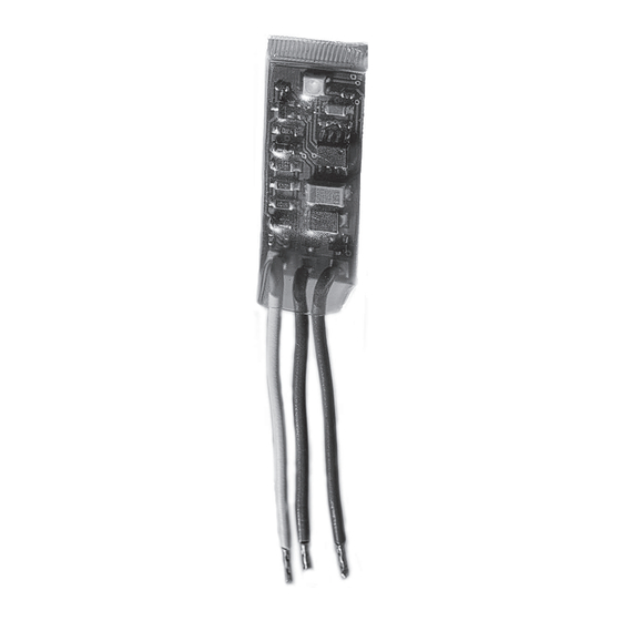
Printed circuit board with components and con-
nection wires to be installed in connection box to
be supplied on site.
Strictly observe the information given in this
and in the instructions for installation of
drives when mounting the M-COM.
!
Details can be found on our website
www.aumueller-gmbh.de
Keep this instruction over the lifetime of the
product.
M-COM
24V
Advertisement

Related Manuals for Aumuller M-COM


Summary of Contents for Aumuller M-COM
- Page 1 • To allow assembly and installation work, each drive may again possible. be run individually - i. e. one locking drive in test run • M-COM allows a smooth exchange of drives in need of repair within the multi-drive system. Warranty claims require proper and profes-...
- Page 2 1: I NSTALLATION NSTALLATION STEP ¢ Mount the drives according the instructions for in- ¢ Connect the multi-drive system to the M-COM and to stallation the drives. the supply line. 24V-drives with version S12 / S3 (soft- In SHEV case t additionally the line end (ware version SW-V2) required.
- Page 3 Factory settings ¢ Connect white wires (WH) of the M-COM. (M-COM is reset). lights red ¢ Put the system - with M-COM - back into operation (see chapter „First commissioning“). 0,5s - 0,5s Communication - to the multi-drive operation - becomes set up.
- Page 4 (per drive 1 time) ¢ Eliminate faults. (1 time blinks = identi ed one drive). ¢ Put the system - with M-COM - back into operation (see chapter „First commissioning“) . ¢ If the LED blinks red, an error is displayed.
Need help?
Do you have a question about the M-COM and is the answer not in the manual?
Questions and answers