Table of Contents
Advertisement
Quick Links
®
If you have a problem, question, or request, call
your local dealer, or Steelcase Line 1 at
888.STEELCASE (888.783.3522)
for immediate action by people who want to help you.
(Outside the U.S.A., Canada, Mexico, Puerto Rico,
and the U.S. Virgin Islands, call: 1.616.247.2500)
Or visit our website: www.steelcase.com
©
2015 Steelcase Inc.
Grand Rapids, MI 49501
U.S.A.
Printed in U.S.A.
Hardware Bag
CABLE
WORKSURFACE
CONTROLLER
CLIP
SCREW
SCREW
X 2
X 42
10-10 X 1.075"
8-15 X 0.625"
SCREW (BLACK)
SCREW (SILVER)
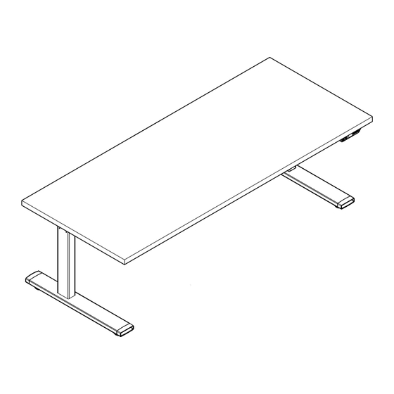
Series 9 - Height Adjustable Tables
CONTROL BOX
FOOT
SCREW
BOLT
X 2
X 2
X 8
10-12 X 2"
M6 X 1.0 X 25MM
SCREW
BOLT
Tools required:
Power Drill
Bit Holder
Long #2 Square
Drive Bit
LEG
BOLT
Socket Adaptor
X 12
(or)
M6 X 1.0 X 12MM
BOLT
Ratchet
10mm Socket
Level
Page 1 of 18
939564905 Rev E
Advertisement
Table of Contents

Related Manuals for Steelcase 9 Series


Summary of Contents for Steelcase 9 Series
- Page 1 BOLT Ratchet 10mm Socket If you have a problem, question, or request, call your local dealer, or Steelcase Line 1 at 888.STEELCASE (888.783.3522) for immediate action by people who want to help you. (Outside the U.S.A., Canada, Mexico, Puerto Rico, Level and the U.S.
- Page 2 IMPORTANT SAFETY INSTRUCTIONS ® When using an electrical furnishing, basic precautions should always be followed, including the following: Read all instructions before using (this furnishing). DANGER - To reduce the risk of electric shock: 1. Always unplug this furnishing from the electrical outlet before cleaning. WARNING - To reduce the risk of burns, fire, electric shock, or injury to persons: 1.
-
Page 3: Table Of Contents
® TABLE OF CONTENTS: PAGE(S): Let’s Get Started!................... Attaching Mounting Brackets to Legs............Attaching Legs to Worksurface..............Attaching Feet to Legs................... 7 - 9 Attaching Control Box & Controller..............Connecting & Routing Cables................ 10 - 11 Attaching Wire Manager & End Caps............12 - 14 Finishing the Table Assembly................. -
Page 4: Let's Get Started
® Let's Get Started! Put down a CLEAN shipping blanket to protect the worksurface Unpack the worksurface and place on the shipping blanket upside-down. • Prepare a large open space to assemble the table. • REMEMBER - You're looking at the UNDERSIDE of the worksurface. Are you sure which side is left or right? •... -
Page 5: Attaching Mounting Brackets To Legs
Attaching Mounting Brackets to Legs ® Layout the lifting columns, ensuring that the wiring receptacle Locate and install each mounting bracket using the M6 x 1.0 X 12MM is faced towards the center of the worksurface. bolts provided. Tighten securely. NOTE: Install 2 bolts, (A), in the back of the mounting bracket before installing the 4 side screws, (B), to ensure that the back of the mounting bracket is flush with the back of the motor box. -
Page 6: Attaching Legs To Worksurface
Attaching Legs to Worksurface ® With the top still upside down on the floor, turn the legs over, and align the mounting brackets Mounting Bracket to the pre-drilled holes in the top. Install one fastener in each of the pre-drilled pilot holes. Then, install the remaining fasteners in each of the remaining holes and tighten ALL screws securely. -
Page 7: Attaching Feet To Legs
Attaching Feet to Legs & Attaching Control Box & Controller ® Locate and install each foot using the M6 X 1.0 X 25MM Locate and install each hat-channel clip using fasteners provided. Tighten securely. bolts provided. Tighten securely. NOTE: The longer portion of the foot should be facing the front of the worksurface. -
Page 8: Attaching Control Box & Controller
Attaching Control Box & Controller (continued) ® Install control box in the pre-determined location, using the pre-drilled holes. Route lifting column cables through the molded-in channels on the underside of the Take care to not damage the cables. control box, and plug into ports 1 and 2. Connect the 120V plug into the control box. - Page 9 Attaching Control Box & Controller (continued) ® NOTE: If the table is plugged into a power source before the Digital Desk Panel Controller is plugged into the control box, the table will not move. 8-15 X 0.625” SCREW If this does occur, disconnect the table from the power source. Then, plug the controller into port A1 of the control box.
-
Page 10: Connecting & Routing Cables
Connecting & Routing Cables ® FILTER NO FILTER Connect the cables to each lifting column and to the control box. Route these cables in the wire management slots provided on the underside of the control box. Refer to the Wiring Guide on page 18 for more information. - Page 11 Connecting & Routing Cables (continued) ® Bundle and tie the excess cable with the twist ties provided with the power Confirm that the controller is plugged into port A1 of the control box, or motor cables so that it is inline with the control box. and only then, plug unit into the power source.
-
Page 12: Attaching Wire Manager & End Caps
Attaching Wire Manager & End Caps ® Install the wire manager to the underside of the worksurface by snapping the inner walls of wire manager into place on the hat-channel clips. The center of the wire manager should be aligned with the center of the worksurface. HAT CHANNEL CLIP SNAP FIT... - Page 13 Attaching Wire Manager & End Caps (continued) ® INTERIOR CHANNEL ‘MOUSE HOLE’ EXTERIOR CHANNEL Route controller cable from the interior channel of the wire manager through the opening of the end cap to END CAP POWER CABLE the exterior channel of the wire manager. Route the power cable from the interior channel of the wire manager to the ‘mouse hole’...
- Page 14 Attaching Wire Manager & End Caps (continued) ® Remove the release liner from the dual lock Align end caps with the wire manager and install on the underside of the worksurface tape on the interior of the end caps. around the outer edges of the lifting columns and mounting brackets. Press down at the locations shown to bond the dual lock tape to the underside of the worksurface.
-
Page 15: Finishing The Table Assembly
Finishing the Table Assembly ® After the table is in place, connect power cord to power supply. Carefully turn the table over (2-person operation), taking care to avoid damaging the controller. NOTE: Do NOT use either lifting column as a brace when turning the table over, as this may cause binding. - Page 16 Finishing the Table Assembly (continued) ® Before articulation, you must synchronize the lifting columns as outlined below. Ensure all cables are clear of moving parts. NOTE: Mounting of CPU and CPU holders: Maximum height for these Before use, the table must be completely leveled, units cannot exceed 20-1/2”.
-
Page 17: Guidelines On Moving The Table
® Guidelines on Moving the Table RIGHT LIFTING COLUMN When possible, the table should be moved in a horizontal (flat) position. If the table must be turned vertically (i.e. standing on a pallet), care must be taken to ensure no side pressure is placed on any of the lifting columns as it is tipped into position, during transport, and when tipped off the pallet at the new location. -
Page 18: Wiring Guide
Once you have completed the wiring, use the wire managers to hold all the cables and minimize possible entanglements. RIGHT LIFTING COLUMN NOTE: Vertical wire management solutions are also available from Details. Contact your local dealer or Steelcase.com for more information. CONTROL FOOT GLIDE LEFT LIFTING...
Need help?
Do you have a question about the 9 Series and is the answer not in the manual?
Questions and answers