
Related Manuals for Frigomat Taylor CH03 Series


Summary of Contents for Frigomat Taylor CH03 Series
- Page 1 PASTORIZZATORI A BAGNOMARIA PASTEURIZERSBAIN MARIE SYSTEM PASTEURISATEURS BAIN-MARIE MANUALE D’USO E MANUTENZIONE OPERATING INSTRUCTION AND MAINTENANCE MANUEL D’UTILISATION ET D’ENTRETIEN Serie-Series-Série CH03 CH04 CH06...
- Page 2 IMPORTANT We recommend that you read this manual fully and carefully before using your appliance. In it in your interest to pay special attention to the warnings marked as follows: Failure to comply with this signal causes very serious risks for heath, death, and permanent damage at medium and long range.
- Page 3 The machine is covered by warranty according to the terms illustrated in the "WARRANTY CARD" supplied. It must be properly filled in and returned to: FRIGOMAT s.r.l., via 1° Maggio, 28 26862 GUARDAMIGLIO (LODI) – ITALIA Please write the serial number of your machine in the field below.
-
Page 4: Table Of Contents
INDEX ………… 1. TRANSPORTATION, HANDLING AND STORAGE ………………………………………… Preliminary inspection ………… Dimensions and weights of packaged machines Indications for decommissioning ………………………………… ………………………………… 2. MARKING AND GRAPHICAL SIGNS 3. GENERAL SAFETY STANDARDS ………………………………………… ………………………………………………… 4. INSTALLATION ………………………………………………… 4.1 Use ………………………………………………… 4.2 Working limits …………………………………………………... -
Page 5: Transportation, Handling And Storage
1 TRANSPORTATION, HANDLING AND STORAGE 1.1 PRELIMINARY INSPECTION AND STORAGE The machine is transported at the risk and danger of the customer. If you notice any damage to the packaging, immediately inform the carrier. Inform the carrier right after opening the package if the machine is damaged even if it is a few days after delivery. -
Page 6: Marking And Graphical Signs
2. MARKING AND GRAPHICAL SIGNS The machine is provided with an identification plate and some pictograms. They must be known along with the manual to guarantee safe use. Machine data plate The adhesive plate applied on the rear permits one to identify the model. - Page 7 Attention! High voltage inside; danger of electrocution. This plate is applied on the cover of the electrical box and warns the operator that it must not be removed for any reason whatsoever, thus avoiding the danger of electrocution which could be fatal. In this case as well, maintenance of internal components is reserved for qualified personnel.
-
Page 8: General Safety Standards
3. GENERAL SAFETY STANDARDS Strictly observe the general safety and accident-prevention standards listed hereafter: Use of the machine is reserved for personnel in good health, responsible and appropriately trained as to allowed use and risks present. Use of the machine is reserved for operators who have read, understood and taken in all that is included in this manual. -
Page 9: Installation
4. INSTALLATION 4.1 USE Appliance suitable for the thermal processing of food mixtures for ice cream, according to use allowed by Law. 4.2 WORKING LIMITS Do not use the machine with inconstant power supplies or +/- 10% beyond the value indicated on the plate or else with the power cable damaged. -
Page 10: Activation
4.5 ACTIVATION TAYLOR declines all and any liability for damage caused by failure to comply with the following indications. This lack of compliance causes the warranty to terminate. Connection of the machine to the water mains must be performed respecting national regulations of the Country where the machine is installed. - Page 11 Make sure that the cold water supply line intended for condensation has pressure values between 1 and 3 BAR (between 100 kPa e 300 kPa) and temperature between 13° and 20°C. Always use new pipes suitable the the IEC 61770 standards.
- Page 12 If the beater motor runs according to the wrong sense, the pump of the bain-marie circuit will subsequently get the same incorrect rotation, with consequent loss of fluid (mono- ethylenic glycol) from the circuit itself. In this case (loss of glycol fluid) check the relevant level inside the tank and, if necessary, restore the correct quantity.
-
Page 13: Safety Devices
5. SAFETY DEVICES Shearing-prevention safety device: Implemented by means of a safety circuit compliant with European standards; it intervenes by blocking the beater motor when the tank cover is opened. Motor overheating safety device: Implemented by means of thermal relays; they protect machine motors from overloads, by signalling a message on the display, emitting an intermittent acoustic signal and are restored directly from the push button control panel. -
Page 14: Operation
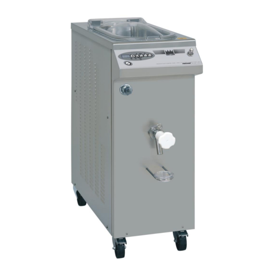
6. OPERATION 6.1 MACHINE 1. Tank lid Close the tank during the working operations. easily removed for cleaning. 2. Shower With extractable hose, it allows the operator to clean the tank, tap and mixer. Never direct the jet of water against the side panels. -
Page 15: Control Panel
6.2 CONTROL PANEL 1. STOP In whatever operating phase the machine is in, pressing the STOP key stops the machine and cancels the function in progress. 2. MIXING / UP (▲) This button has 2 functions: 1. PEB 30 MEC, PEB 60 MEC: With the machine at STOP, by pressing the MIXING key, only the beater motor starts up;... - Page 16 2. During programming, by pressing the UP button, it is possible to increase value of the selected parameter. 3. SEMI-AUTOMATIC / CONFIRM (◄►) This button has 4 functions: 1. With the machine at STOP, pressing the SEMI-AUTOMATIC key accesses the semi-automatic thermal processing cycle where it is possible to select the maximum temperatures and stand-by times desired.
- Page 17 5. LOW PASTEURIZATION 65°C This button has 3 functions: 1. With machine STOP, pressing PASTEURIZATION key automatically starts the pasteurization cycle at 65°C with consequent preservation at 4°C. 2. Press the LOW PASTEURIZATION key for at least 3” with the machine at LOW PASTEURIZATION mode to temporarily display the instantaneous bain-marie fluid temperature.
-
Page 18: High Pasteurization 85°C
6.3 HIGH PASTEURIZATION 85°C - Make sure that the gate valve of cold water for condensation is open (only water mod.). - Make sure the master switch is closed and that the machine is powered correctly. - Make sure the mixture dispenser tap is closed and that the tank beater is assembled correctly. -
Page 19: Low Pasteurization 65°C
6.4 LOW PASTEURIZATION 65°C - Make sure that the gate valve of cold water for condensation is open (only water mod.). - Make sure the master switch is closed and that the machine is powered correctly. - Make sure the mixture dispenser tap is closed and that the tank beater is assembled correctly. -
Page 20: Semi-Automatic Processing
6.5 SEMI-AUTOMATIC PROCESSING - Make sure that the gate valve of cold water for condensation is open (only water mod.). - Make sure the master switch is closed and that the machine is powered correctly. - Make sure the mixture dispenser tap is closed and that the tank beater is assembled correctly. - Page 21 - The leds of the UP (▲), ENTER (◄►) and DOWN (▼) keys will flash and the display will show the numbers of the time to be set, between 0’ and 10 hours: press the “UP (▲)” and “DOWN (▼)” keys to increase or decrease the value. At the desired value, press ENTER (◄►) to store the set-up values and to start the working cycle.
-
Page 22: Preservation At 4°C
6.6 PRESERVATION at 4°C Following a voluntary interruption, by the user, during the cooling phase of one of the cycles of the heat treatment described above, it may be useful to restart the machine from the cooling phase which has been interrupted. In order to carry out a colling cycle only, please proceed as follows: - Press simultaneously the “STOP”... -
Page 23: Product Drawing From Tank
6.7 DRAWING OF THE PRODUCT FROM THE TANK To extract the product in the tank, proceed as follows: - If the product has been in storage for more than 2 hours, before starting the drawing press the "MIXER" key to turn on the agitator motor. Let the agitator turn for a few seconds to ensure that the entire mass of product in the tank is well mixed and not separated. -
Page 24: Maintenance
7. MAINTENANCE 7.1 ROUTINE MAINTENANCE (INTENDED FOR USER) The fats present in the ice cream mixtures are ideal fields for the proliferation of bacterial loads and mould. To eliminate this serious problem, all the parts which come into contact with the product must be thoroughly washed and sanitised by careful procedures and using suitable sanitising products. - Page 25 Pour the maximum admitted load of cold drinking water into the tank to rinse the surfaces which were just treated with the sanitizer. Drain the rinse water and turn the machine off. When pre-washing is over, all the removable parts in contact with the product must be disassembled and sanitised in a separate tank.
- Page 26 Emerge the components disassembled previously into the tank with the sanitizer and brush the surfaces with care. Pay special attention to the inner duct of the beater shaft. REMOVING AND CLEANING THE TAP Unscrew the ring nut of the tap (A). ...
- Page 27 Never use any type of solvents and/or thinners to preserve the plastic parts and gaskets during washing. Chemical sanitising products must be used in compliance with standards in force and with the utmost caution. During sanitising operations, do not touch parts with tissues, sponges, rags or any other non-sterile material.
-
Page 28: Extraordinary Maintenance
7.3 EXTRAORDINARY MAINTENANCE (INTENDED FOR QUALIFIED PERSONNEL) These operations are reserved exclusively for authorised qualified personnel. TAYLOR S.r.l. will not be held liable for damage to objects or harm to persons which occur due to failure to comply with the above. Refer to the following instructions to program the circuit board: 1. - Page 29 “MEB²” BOARD PROGRAMMING TABLE (**) DESCRIPTION STEP CH03 CH04 CH06 Machine model Tank probe correction (TEV) -12,7° +12,7° 0,5°C Fluid tank -12,7° +12,7° 0,5°C correction (TEF) Beater option OFF for 0=OFF preservation 1=ON AUTO Tank overtemperature compensation when -12,7° +12,7° 0,5°C TEV>40°C Anti-freeze intervention temp.
-
Page 30: Instructions For Identifying Failures
8. INSTRUCTIONS FOR IDENTIFYING FAILURES 8.1 MANAGEMENT OF ALARMS MESSAGE DESCRIPTION REMEDIES The cover is open or a safety device which stops the beater is active. Make sure that the cover is The buzzer emits an intermittent acoustic closed and positioned properly. signal. -
Page 31: Troubleshooting
8.2 TROUBLESHOOTING PROBLEM PROBABLE CAUSES REMEDIES Master switch open Close the switch The machine does not start Electrical anomaly Contact the technician (STOP button off) Fuses blown Contact the technician During the stand-by or Press any key to reactivate the “Energy saving”... - Page 32 9 APPENDICI / APPENDICES / ANNEXES / ANHANG / APENDICES 9.1 Dati tecnici / Machine specifications / Caractéristiques techniques Modello Alimentazione Condensazione Potenza Altezza Larghezza Profondità Peso Gas R404 Model Current Cooling Power Height Width Dept Weight Modell Stromart Kühlung Nennleistung Höle Breite...
- Page 33 9.2 CH03-CH04-CH06 Schema circuito frigorifero / Refrigerant circuit diagram / Schéma du circuit frigorifique APPENDICI - 2...
- Page 34 9.3 IMPIANTO ELETTRICO / ELECTRIC SYSTEM / GROUPE ELECTRIQUE Lo schema elettrico funzionale ed il lay-out del box elettrico, specifico per ogni modello, è collocato sulla parte esterna del coperchio del box stesso. The functional wiring diagram and the electric box lay-out, different for each model are located on the box cover.
-
Page 35: Technical Data
9.4 RICAMBI / SPARE PARTS / PIECES DETACHEES Per la richiesta delle parti di ricambio, si raccomanda di indicare sempre il numero di codice relativo e la denominazione riportata sulla legenda di ciascuna tavola. Si raccomanda inoltre di comunicare sempre il modello ed il numero di matricola della macchina, nonché le caratteristiche della stessa (voltaggio, frequenza e fasi), facilitando in tal modo l’identificazione del particolare. - Page 36 MIXER – TAV 1/1 OPTIONAL 5 - APPENDICI...
- Page 37 MIXER - TAV 1/1 OPTIONAL COD. DESCRIZIONE DESCRIPTION DESCRIPTION BESCHREIBUNG DESCRIPTION Coperchio Emulsification unit Couvercle de A02.36967 Mischgruppendeckel Tapa emulsificador l’émulsionneur emulsionatore cover Carenatura anteriore Emulsification unit Capotage antérieur Vordere Abdeckung Carenado anterior A02.36968 de l’émulsionneur emulsionatore front fairing Mischgruppe emulsificador Carenatura posteriore Emulsification unit...
- Page 38 TAV 1/1 GRUPPO RUBINETTO – COCK ASSEMBLY - GROUPE ROBINET - GRUPPE ABGABEHAHN – GRUPO GRIFO 7 - APPENDICI...
- Page 39 TAV 1/1 GRUPPO RUBINETTO – COCK ASSEMBLY - GROUPE ROBINET - GRUPPE ABGABEHAHN – GRUPO GRIFO COD. DESCRIZIONE DESCRIPTION DESCRIPTION BESCHREIBUNG DESCRIPTION P02.174 Maniglia Knob Poignée Schraubgriff Manivela B09.203 Perno di guida Pivot Boulon de guidage Führungsschraube Perno de guía P02.175 Boccola Bush...
- Page 40 CH03/s02 – TAV 1/7 9 - APPENDICI...
- Page 41 PEB CH03/s02 – TAV 1/7 COD. DESCRIZIONE DESCRIPTION DESCRIPTION BESCHREIBUNG DESCRIPTION A02.40264 Pannello laterale Left side panel Panneau latéral Seitenpaneel Panel lateral Z56.37923 Gruppo isolamento Insulation unit Groupe isolant Isolationsgruppe Grupo aislamiento P03.218 Coperchio Cover Couvercle Deckel Tapa B09.215 Vite per cerniera Screw for hinge Vis pour fermoir Scharnierschraube...
- Page 42 CH03/s02 – TAV 2/7 11 - APPENDICI...
- Page 43 CH03/s02 – TAV 2/7 COD. DESCRIZIONE DESCRIPTION DESCRIPTION BESCHREIBUNG DESCRIPTION P02.165 Tappo Agitatore Mixer plug Bouchon du Brasseur Stöpsel Rührwerk Tapón Agitador Couronne mobile Girante Ø 112 Disk wheel Ø 112 Drehscheibe Ø 112 Rueda Ø 112 P02.207 Ø 112 400/50/3 –...
- Page 44 CH03/s01 – TAV 3/7 13 - APPENDICI...
- Page 45 CH03/s01 – TAV 3/7 COD. DESCRIZIONE DESCRIPTION DESCRIPTION BESCHREIBUNG DESCRIPTION B09.205 Portabulbo Bulb holder Porte-cuvette Haltewulst Portabola Abrazadera B13.019 Fascetta inox 12-20 S.S. clamp 12-20 Collier inox 12-20 INOXschelle 12-20 inoxidable 12-20 Compressore Compressor Compresseur Kompressor Compresor B01.37654 380-420/50/3 380-420/50/3 380-420/50/3 380-420/50/3 380-420/50/3...
- Page 46 CH03/s02 – TAV 4/7 15 - APPENDICI...
- Page 47 CH03/s02 – TAV 4/7 COD. DESCRIZIONE DESCRIPTION DESCRIPTION BESCHREIBUNG DESCRIPTION B09.205 Portabulbo Bulb holder Porte-cuvette Haltewulst Portabola Abrazadera B13.019 Fascetta inox 12-20 S.S. clamp 12-20 Collier inox 12-20 INOXschelle 12-20 inoxidable 12-20 A07.032 Filtro Filter Filtre Filter Filtro Orifice for Orifizio per valvola Orifice pour soupape Öffnung für thermost.
- Page 48 CH03/s02 – TAV 5/7 VERSIONE CONDENSATA AD ACQUA WATER COOLED VERSION REFROIDISSEMENT À EAU WASSERGEKÜHLT ENFRIADO POR AGUA 17 - APPENDICI...
- Page 49 CH03/s02 – TAV 5/7 COD. DESCRIZIONE DESCRIPTION DESCRIPTION BESCHREIBUNG DESCRIPTION A10.001 Rubinetto Cock Robinet Ausgabehahn Grifo Guarnizione 1/2” Basket 1/2” Joint 1/2” Dichtung 1/2” Guarnición 1/2” P06.085 Manicotto 1/2”- 1/2 Sleeve 1/2”- 1/2 Manchon 1/2”- 1/2 Muffe 1/2”- 1/2 Manguito 1/2”- 1/2 R02.012 Manicotto 1/2”-3/4”...
- Page 50 CH03/s02 – TAV 6/7 19 - APPENDICI...
- Page 51 CH03/s02 – TAV 6/7 COD. DESCRIZIONE DESCRIPTION DESCRIPTION BESCHREIBUNG DESCRIPTION Anschluß und Assieme raccordo Pump delivery Groupe raccord sortie Grupo unión salida R02.101 Pumpenausgang uscita pompa connection assembly de pompe bomba zusammen E01.38333 Pompa fluido Fluid pump Pompe fluide Flüssigkeitspumpe Bomba fluido Curva M-F 1”-1/4”...
- Page 52 CH03/s02 – TAV 7/7 21 - APPENDICI...
- Page 53 CH03/s02 – TAV 7/7 COD. DESCRIZIONE DESCRIPTION DESCRIPTION BESCHREIBUNG DESCRIPTION Carte du tableau E15.41676 Scheda pulsantiera Pushbutton card Tastenfeldkarte( tarjeta pulsadores poussoirs M02.41677 Etichetta anteriore Front label Etiquette antérieure Vorderes Schild Etiqueta anterior Remote control D02.061 Teleruttore 24 V Télérupteur 24 V Fernschalter 24 V telerruptor 24 V switch 24 V...
- Page 54 CH04/s02 – TAV 1/6 23 - APPENDICI...
- Page 55 CH04/s02 – TAV 1/6 COD. DESCRIZIONE DESCRIPTION DESCRIPTION BESCHREIBUNG DESCRIPTION A02.40138 Pannello laterale SX Left side panel Panneau latéral SX Seitenpaneel links Panel lateral IZQD. Z56.37963 Gruppo isolamento Insulation unit Groupe isolant Isolationsgruppe Grupo aislamiento P03.219 Coperchio Cover Couvercle Deckel Tapa B09.215 Vite per cerniera...
- Page 56 CH04/s02 – TAV 2/6 OPTIONAL 25 - APPENDICI...
- Page 57 CH04/s02 – TAV 2/6 COD. DESCRIZIONE DESCRIPTION DESCRIPTION BESCHREIBUNG DESCRIPTION P02.165 Tappo Agitatore Mixer plug Bouchon du Brasseur Stöpsel Rührwerk Tapón Agitador P02.164 Girante Disk wheel Couronne mobile Drehscheibe Rueda Disk wheel holding Tuyau porte- Röhrchen B06.357 Canotto porta girante Barra porta rueda tube couronne mobile...
- Page 58 CH04/s02 – TAV 3/6 27 - APPENDICI...
- Page 59 CH04/s02 – TAV 3/6 COD. DESCRIZIONE DESCRIPTION DESCRIPTION BESCHREIBUNG DESCRIPTION B09.205 Portabulbo Bulb holder Porte-cuvette Haltewulst Portabola Abrazadera B13.019 Fascetta inox 12-20 S.S. clamp 12-20 Collier inox 12-20 INOXschelle 12-20 inoxidable 12-20 Compressore Compressor Compresseur Kompressor Compresor B01.40133 380-420/50/3 380-420/50/3 380-420/50/3 380-420/50/3 380-420/50/3...
- Page 60 CH04/s02 – TAV 4/6 29 - APPENDICI...
- Page 61 CH04/s02 – TAV 4/6 COD. DESCRIZIONE DESCRIPTION DESCRIPTION BESCHREIBUNG DESCRIPTION A10.001 Rubinetto Cock Robinet Ausgabehahn Grifo Guarnizione 1/2” Basket 1/2” Joint 1/2” Dichtung 1/2” Guarnición 1/2” P06.085 Manicotto 1/2”- 1/2 Sleeve 1/2”- 1/2 Manchon 1/2”- 1/2 Muffe 1/2”- 1/2 Manguito 1/2”- 1/2 R02.012 Manicotto 1/2”-3/4”...
- Page 62 CH04/s02 – TAV 5/6 31 - APPENDICI...
- Page 63 CH04/s02 – TAV 5/6 COD. DESCRIZIONE DESCRIPTION DESCRIPTION BESCHREIBUNG DESCRIPTION Assieme raccordo Pump delivery Groupe raccord sortie Anschluß und Grupo unión salida R02.101 uscita pompa connection assembly de pompe Pumpenausgang bomba zusammen E01.38333 Pompa fluido Fluid pump Pompe fluide Flüssigkeitspumpe Bomba fluido Curva M-F 1”-1 1/4”...
- Page 64 CH04/s02 – TAV 6/6 33 - APPENDICI...
- Page 65 CH04/s02 – TAV 6/6 COD. DESCRIZIONE DESCRIPTION DESCRIPTION BESCHREIBUNG DESCRIPTION Carte du tableau E15.41676 Scheda pulsantiera Pushbutton card Tastenfeldkarte tarjeta pulsadores poussoirs M02.41677 Etichetta anteriore Front label Etiquette antérieure Vorderes Schild Etiqueta anterior Remote control D02.061 Teleruttore 24 V Télérupteur 24 V Fernschalter 24 V telerruptor 24 V switch 24 V...
- Page 66 CH06/s03 – TAV 1/6 35 - APPENDICI...
- Page 67 CH06/s03 – TAV 1/6 COD. DESCRIZIONE DESCRIPTION DESCRIPTION BESCHREIBUNG DESCRIPTION Piastra rinforzo Plaquette pour A20.38648 Hinge plate Scharnierplatte Lamina de bisagra cerniera fermoir A02.40138 Pannello laterale SX Side panel SX Panneau latéral SX Seitenpaneel SX Panel lateral SX Z56.38509 Gruppo isolamento Insulation unit Groupe isolant Isolationsgruppe...
- Page 68 CH06/s03 – TAV 2/6 OPTIONAL 37 - APPENDICI...
- Page 69 CH06/s03 – TAV 2/6 COD. DESCRIZIONE DESCRIPTION DESCRIPTION BESCHREIBUNG DESCRIPTION P02.165 Tappo Agitatore Mixer plug Bouchon du Brasseur Stöpsel Rührwerk Tapón Agitador Disk wheel Couronne mobile Drehscheibe P02.164 Girante Ø 140 h 15 Rueda Ø 140 h 15 Ø 140 h 15 Ø...
- Page 70 CH06/s03 – TAV 3/6 39 - APPENDICI...
- Page 71 CH06/s03 – TAV 3/6 COD. DESCRIZIONE DESCRIPTION DESCRIPTION BESCHREIBUNG DESCRIPTION B09.205 Portabulbo Bulb holder Porte-cuvette Haltewulst Portabola Compressore Compressor Compresseur Kompressor Compresor B01.43303 400/50/3 400/50/3 400/50/3 400/50/3 400/50/3 Compressore Compressor Compresseur Kompressor Compresor B01.43321 220/60/3 220/60/3 220/60/3 220/60/3 220/60/3 Orifizio per valvola Orifice for Orifice pour soupape Öffnung für thermost.
- Page 72 CH06/s03 – TAV 4/6 41 - APPENDICI...
- Page 73 CH06/s03 – TAV 4/6 COD. DESCRIZIONE DESCRIPTION DESCRIPTION BESCHREIBUNG DESCRIPTION A10.001 Rubinetto Cock Robinet Ausgabehahn Grifo Guarnizione 1/2” Basket 1/2” Joint 1/2” Dichtung 1/2” Guarnición 1/2” P06.085 Manicotto 1/2”- 1/2 Sleeve 1/2”- 1/2 Manchon 1/2”- 1/2 Muffe 1/2”- 1/2 Manguito 1/2”- 1/2 R02.012 Manicotto 1/2”-3/4”...
- Page 74 CH06/s03 – TAV 5/6 43 - APPENDICI...
- Page 75 CH06/s03 – TAV 5/6 COD. DESCRIZIONE DESCRIPTION DESCRIPTION BESCHREIBUNG DESCRIPTION Tuyau T10.090 Tubo sfiato Drain pipe Überlaufrohr Tubo de desfogue d’échappement Serbatoio fluido Réservoir de fluide Kompl. Depósito fluido Z61.38527 Additional fluid tank compl. compl. Flüssigkeitsbehälter compl. Tappo serbatoio Bouchon du réservoir Verschluß...
- Page 76 CH06/s03 – TAV 6/6 45 - APPENDICI...
- Page 77 CH06/s03– TAV 6/6 COD. DESCRIZIONE DESCRIPTION DESCRIPTION BESCHREIBUNG DESCRIPTION M02.41677 Etichetta anteriore Front label Etiquette antérieure Vorderes Schild Etiqueta anterior Carte du tableau E15.41676 Scheda pulsantiera Pushbutton card Tastenfeldkarte tarjeta pulsadores poussoirs Remote control D02.061 Teleruttore 24 V Télérupteur 24 V Fernschalter 24 V telerruptor 24 V switch 24 V...
- Page 78 NOTE / NOTES / NOTES / BEMERKUNG / NOTA...
- Page 80 FRIGOMAT s.r.l., via 1° Maggio 26862 GUARDAMIGLIO (LO) – ITALIA tel. 0377.415011 – Fax. 0377.451079 www.frigomat.com info@frigomat.com 2019...
Need help?
Do you have a question about the Taylor CH03 Series and is the answer not in the manual?
Questions and answers