Table of Contents
Advertisement
Advertisement
Table of Contents

Related Manuals for Nautilus Inspiration 4-Station


Summary of Contents for Nautilus Inspiration 4-Station
- Page 1 Core Health & Fitness Nautilus® Inspiration® 4-Station OWNER’S MANUAL...
-
Page 2: Table Of Contents
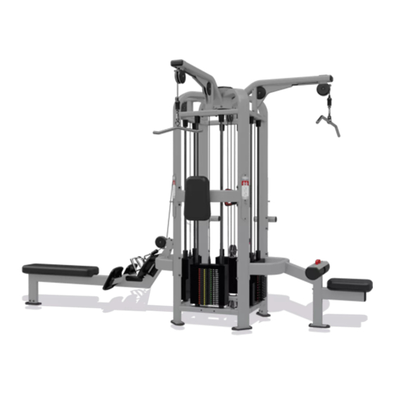
TABLE OF CONTENTS PRODUCT SPOTLIGHT ............................. 2 IMPORTANT SAFETY INSTRUCTIONS ............................. 3 ..................5 IMPORTANT LABEL LOCATIONS INSTALLATION ............................. 7 ..................8 LOW ROW TRICEP PRESS ..................12 LAT PULLDOWN ..................16 CABLE CROSS ..................20 STRENGTH PRODUCT USE ............................27 MAINTENANCE ............................30 SUPPORT AND SERVICE ............................ - Page 3 PRODUCT SPOTLIGHT 9NP-M9601 Inspiration 4-Station Overall Weight Width Length Height Max User Weight 1732 lbs (396 kg) 60 in (81 cm) 131 in (208 cm) 96 in (154 cm) 350 lbs (159 kg) All products may be covered by US and Foreign Patents and Patents Pending.
-
Page 4: Important Safety Instructions
Read all warnings posted on the machine. Health related injuries may result from incorrect or excessive use of exercise equipment. NAUTILUS strongly recommends you to encourage your members to discuss their health program or fitness regimen with a health care professional, especially if you or they have not exercised for several years, are over 35, or have known health conditions. -
Page 5: Maintenance
Cables pose an extreme liability if used when frayed. Always replace any cable at first sign of wear. (Consult Nautilus if uncertain or if you have questions regarding wear). Routinely inspect all cable couplers that join movement arms to the cables and replace at the first sign of wear. -
Page 6: Important Label Locations
IMPORTANT LABEL LOCATIONS 731-8118 731-8118 Instruction Placards Instruction Placards *See page 28 731-7223-01 731-7223-01 731-7223-02 731-7223-02 NOTES: OVERLAY NOT TO BE AFFECTED BY WASH/WIPE USING ALCOHOL (ISOPROPYL), AMMONIA AND/OR A 5% SODIUM HYPOCHLORITE TO WATER SOLUTION (CLOROX). DRAWING ARTWORK AND DIMENSIONS ARE FOR REFERENCE ONLY. REFER TO ART FILE 050-2198.PDF FOR CORRECT ARTWORK, COLORS AND EXACT DIMENSIONS. - Page 7 731-0512 731-7223-01 731-7223-02 ADJUSTMENT INSTRUCTIONS TO ADJUST THE FRONT ROLLER, LOOSEN THE JAM NUT ON THE SET SCREW WITH TROLLEY INSTALLED ONTO POST REMOVE (2) FASTENERS AND WASHERS IN END CAP. REMOVE END CAP, PLACE ASIDE TO BE REINSTALLED LATER. TIGHTEN THE SET SCREW, GRAB HANDLE AND ROCK IT UP AND DOWN, IF IT DOES NOT MOVE, THEN PULL PIN AND SLIDE TOLLEY UP AND DOWN (MAKE SURE THERE...
-
Page 8: Required Tools
INSTALLATION Required Tools: • #2 Phillips Screwdriver • 4mm Allen Key • 5mm Allen Key • 6mm Allen Key • 8mm Allen Key • 16mm Socket • Ratchet Wrench • 16mm Open-Ended Wrench • 13mm Open-Ended Wrench • 10mm Open-Ended Wrench Parts List Description 731-3157-XX... - Page 9 LOW ROW Use a #2 phillips screwdriver to remove the two (2) M3.5 x 13mm self tapping screws (731-3186) from the frame, then remove the cap (731-3185). Use a 5mm allen key to loosen the four (4) set screws located at the bottom of the weight stack guide rods, once the set screws are loose the guide rods should...
- Page 10 Starting from the bottom of the weight stack (731-3641), carefully slide each weight plate down the guide rods. Once the entire weight stack has been installed, replace the guide START rod caps, reinstall the rods back into place, and tighten the set screws loosened in step 3.
- Page 11 Use a 16mm socket and a 16mm open-ended wrench to secure the low row weldment to the tower frame using four (4) pieces each of the M10 x 140mm bolts (110-3783) and M10 nylock nuts (731-0363), eight (8) pieces of the M10 flat washer (731- 0367), and two (2) pieces of the weldment mount bracket (731- 3221).
- Page 12 Finish securing the upper weldment to the tower frame using three (3) pieces each of the M10 x 30mm bolt and M10 nylock nut, and six (6) pieces of the M10 flat washer. . 10 Ensure that the cable is routed .
-
Page 13: Tricep Press
Use a 10mm open-ended wrench to secure the cable (731- 3646) to the weight stack then use a 16mm open-ended wrench to tighten the M10 jam nut to lock the cable in place. . 13 TRICEP PRESS Use a 5mm allen key to loosen the four (4) set screws located at the bottom of the weight stack guide rods, once the set screws... - Page 14 Starting from the bottom of the weight stack (731-3204), carefully slide each weight plate down the guide rods. Once the entire weight stack has been installed, replace the guide rod caps, reinstall the rods back START into place, and tighten the set screws loosened in step 14.
- Page 15 Use a 16mm socket and a 16mm open-ended wrench, secure the back rest weldment to the tower frame using four (4) pieces each of the M10 x 140mm bolt and M10 nylock nut, eight (8) pieces of the M10 flat washer, and two (2) pieces of the bracket mount.
- Page 16 Finish securing the upper weldment to the tower frame using three (3) pieces each of the M10 x 30mm bolt and M10 nylock nut, and six (6) pieces of the M10 flat washer. . 22 Ensure the cable is routed properly.
-
Page 17: Lat Pulldown
LAT PULLDOWN Use a 5mm allen key to loosen the four (4) set screws located at the bottom of the weight stack guide rods, once the set screws are loose the guide rods should drop down. . 25 Swing the guide rods forward out of the machine then remove the guide rode stop caps. - Page 18 Use a 4mm allen key to secure the placard to the frame using three (3) pieces of the M6 x 16mm flat head machine screw, then attach the lat pulldown placard(731-7351) and the add- on decal to the placard. . 28 Set the lat pulldown weldment (731-3648-XX) into place.
- Page 19 Set the lat pulldown weldment into place. . 31 Use a 16mm socket and a 16mm open-ended wrench to secure the upper low row weldment to the tower frame using two (2) pieces each M10 x 75mm bolt and M10 nylock nut, four (4) pieces of the M10 washer, and one (1) piece of the 76.2mm bracket connector.
- Page 20 Ensure the cable is routed properly. . 34 Use a 10mm open-ended wrench to secure the cable to the weight stack then use a 16mm open-ended wrench to tighten the M10 jam nut to lock the cable in place. . 35 Page 19...
-
Page 21: Cable Cross
CABLE CROSS Use a 5mm allen key to loosen the four (4) set screws located at the bottom of the weight stack guide rods, once the set screws are loose the guide rods should drop down. . 36 Swing the guide rods forward out of the machine then remove the guide rode stop caps. - Page 22 Use a 4mm allen key to secure the placard to the frame using three (3) pieces of the M6 x 16mm flat head machine screw, then attach the cable cross decal (731-7348), the trolley instructions decal (731-8118), and the add-on decal to the placard.
- Page 23 Insert the upper support weldment (731-3188-XX) into the guide tube, then use an 8mm allen key to secure the weldment to the guide tube using one (1) piece of the M12 x 25mm flat head machine screw (731-3161). . 42 Install the pulley assembly (731- 0731) into the upper support weldment, then use a 16mm...
- Page 24 Use a 16mm socket and a 16mm open-ended wrench to secure the lower post weldment (731- 3157-XX) to the tower frame using four (4) pieces each of thee M10 x 75mm bolt and M10 nylock nut, and eight (8) pieces of the M10 flat washer.
- Page 25 Ensure the cable is routed properly. See Fig. 48-Fig. 52 . 48 . 49 . 50 Page 24...
- Page 26 . 51 . 52 Use a 13mm open-ended wrench to secure the cable to the trolley using one (1) piece of the M8 nylock nut (731-0365). . 53 Page 25...
- Page 27 Install the end cap (731-0209) into the end of the lat pull down weldment. . 54 Reinstall the tower cap and using a #2 phillips screwdriver, reinstall the two (2) M3 x 13mm self- tapping screws. . 55 Page 26...
- Page 28 It is the sole responsibility of the purchaser of Nautilus Inspiration Strength products to read the owner’s manual, review the following pages and instruct all individuals, whether they are the end user or supervising personnel on proper usage of the equipment.
- Page 29 MULTI STATION MULTI STATION CABLE STATION LOW ROW CHEST PRESS BICEPS CURL AB/ADDUCTION AB CRUNCH WWW.NAUTILUSSTRENGTH.COM WWW.NAUTILUSSTRENGTH.COM U.S 800.503.1221 U.S 800.503.1221 . 56 - Cable Station Instructions . 57 - Low Row Instructions Page 28...
- Page 30 MULTI STATION MULTI STATION TRICEPS PRESS LAT PULL DOWN WWW.NAUTILUSSTRENGTH.COM WWW.NAUTILUSSTRENGTH.COM U.S 800.503.1221 U.S 800.503.1221 . 58 . 59 - Triceps Press Instructions - Lat Pull Down Instructions Page 29...
- Page 31 MAINTENANCE TOOLS Working on this product will require basic and/or sometimes specialty tools based on the type of service that will be performed at any time. To assist, we recommend having the tools listed available when performing maintenance. Tool Socket Set, SAE Screwdriver Set, Phillips Socket Set, Metric Screwdriver Set, Flat...
-
Page 32: Maintenance Schedule
With durable, high performance components, this equipment is designed for heavy usage with minimal maintenance required. To keep it in top condition, perform regular daily, weekly and monthly preventive maintenance routines out- lined below. The safety and integrity of this machine can only be maintained when the equipment is regularly examined for damage and wear and repaired. - Page 33 Note – do not use cleaners that contain solvents, alcohol or abrasives. Inspection Visual inspection of your Nautilus® Inspiration Strength® units will insure a safe environment for your clients and alert you to any issues that may require maintenance prior to equipment failure. Proper, timely visual inspection is a critical component to the long term care of your product.
- Page 34 WARNING: Replace all worn cables immediately. The following conditions indicate some types of wear. Torn or Cracked Cable Sheath that exposes cable Stretched Cable Sheath Kink in the Cable Lubrication Proper cleaning lubrication of guide rods will insure that each machine operates at its highest potential and that your clients continue to enjoy a smooth efficient motion while exercising.
- Page 35 Service Bulletins, and other information. The resources include: • Contact number and email for Technical Support Go to https://support.corehandf.com/ for support information and information on all Nautilus products. • Updated Owner’s Manual, Installation Instructions, Service Bulletins, Instructional Videos, and other information. https://support.corehandf.com/INSPIRATION •...
- Page 36 © 2019 CORE HEALTH & FITNESS, LLC PART NUMBER 620-8707, REV A...
Need help?
Do you have a question about the Inspiration 4-Station and is the answer not in the manual?
Questions and answers