Sonance Sonamp ASAP3D SE Instruction Manual
Hide thumbs
Also See for Sonamp ASAP3D SE:
- Instruction manual (17 pages) ,
- Supplementary manual (9 pages) ,
- Specification sheet (2 pages)
Table of Contents
Advertisement
Quick Links
Advertisement
Table of Contents

Related Manuals for Sonance Sonamp ASAP3D SE


Summary of Contents for Sonance Sonamp ASAP3D SE
- Page 1 ASAP3D SE ® ONAMP TEREO OWER MPLIFIER INSTRUCTION MANUAL...
-
Page 2: Important Safety Instructions
A S A P 3 D S E S ® O N A M P T E R E O O W E R M P L I F I E R Important Safety Instructions D. The amplifier does not appear to be operating properly or exhibits a marked change in performance. -
Page 3: Design And Features
Introduction IR Control The ASAP3D SE has IR Input connections that allow its Thank you for purchasing the Sonance ASAP3D SE amplifier. automatic input switching, volume, muting and BBE to be When properly installed, this amplifier will give you many controlled by an IR keypad controller. - Page 4 • If they’ve already been installed, remove the amplifier’s ASAP3D SE. An optional Rack-Mount Filler Panel is available stick-on feet before using the included rack-mount (Sonance part #92729) that allows a single ASAP3D SE to be accessories. mounted in a 1U rack space.
-
Page 5: Powering The Amplifier
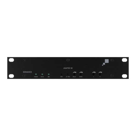
A S A P 3 D S E S ® O N A M P T E R E O O W E R M P L I F I E R RONT ANEL Status Standby and Switching Delay and Input LEDs AC Trigger... -
Page 6: Audio Input Connections
A S A P 3 D S E S ® O N A M P T E R E O O W E R M P L I F I E R Audio Input Connections Wiring the Removable Quick Connectors ’... -
Page 7: Control Inputs/Outputs
12V DC trigger signal whenever the Local source is ON. This trigger can be used to control other devices, such as Control Inputs/Outputs Sonance AL2/AS2 automatic secondar y switches, other Sonamps or 12V DC relays. ’ M P O R TA N T... -
Page 8: Front Panel Indicators And Controls
IGURE designed for connection of IR emitters IR P sets the maximum volume level that both amplifier channels like the Sonance E1, E2, VE1 and VE2. will achieve when responding to IR volume commands. UTPUT The connectors accept 3.5mm mono ONNECTORS Volume commands above that level will be ignored. -
Page 9: Specifications
AC T [AC Trigger] Pinhole Switch BBE Sound Enhancement The AC T pinhole switch (see Figure The Sonamp ASAP3D SE incorporates 21 ) lets the ASAP3D SE determine the ® Sound Enhancement. The BBE precise voltage appearing at its AC process improves music’s presence and... -
Page 10: Installation Examples
The illustrations on these pages show the wide variety of audio and audio/video systems that can be assembled using one or more Sonamp ASAP3D SE amplifiers. Your local Authorized Sonance Dealer is an expert in audio/video system planning and installation. Sonance strongly recommends that you work with your dealer to ensure that your system is properly planned, assembled and installed. - Page 11 A S A P 3 D S E S ® O N A M P T E R E O O W E R M P L I F I E R ASAP3D SE System with IR Triggering Figure 25 shows the typical system connections when triggering the ASAP3D SE via IR from a keypad controller or other IR control device.
- Page 12 A S A P 3 D S E S ® O N A M P T E R E O O W E R M P L I F I E R ASAP3D SE System with Individual Zone IR Controller Figure 26 shows the typical system connections when using the ASAP3D SE as a sub-zone amplifier, being driven by the audio signal from one zone of a multi-zone controller.
-
Page 13: Appendix 1: Changing The Mono Variable Output To A Fixed Output Level
A S A P 3 D S E S ® O N A M P T E R E O O W E R M P L I F I E R Appendix 1: Changing the Mono Variable Output to a Fixed Output Level The M is factory-set to Variable via a jumper on the amplifier PCB. -
Page 14: Appendix 3: Setting Source Turn-On Volume For Ir Switching Mode Operation
A S A P 3 D S E S ® O N A M P T E R E O O W E R M P L I F I E R Appendix 3: Setting Source Turn-On Volume for IR Switching Mode Operation The installer/user can set the turn-on volume for the Local (B) source when using IR commands. - Page 15 Sonance Dealer/Distributor, will be free from defective workmanship and materials for the period stated below. Sonance will at its option and expense during the warranty period, either repair the defect or replace the Product with a new or remanufactured Product or a reasonable equivalent.
- Page 16 Due to continuous product improvement, all features and specifications are subject to change without notice. For the latest Sonance product specification information visit our website: www.sonance.com SONANCE • 212 Avenida Fabricante • San Clemente, CA 92672-7531 USA • (800) 582-7777 or (949) 492-7777 FAX: (949) 361-5151 • Technical Support: (800) 582-0772 w w w .
Need help?
Do you have a question about the Sonamp ASAP3D SE and is the answer not in the manual?
Questions and answers