
Related Manuals for Advantech USB-5820


Summary of Contents for Advantech USB-5820
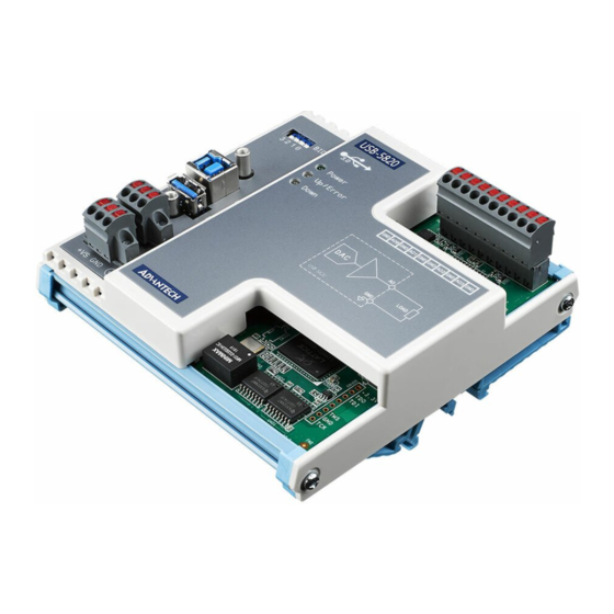
- Page 1 User Manual USB-5820 4-ch, 16-bit, 200 kS/s Isolated Analog Output USB 3.0 I/O Module...
- Page 2 This documentation and the software included with this product are copyrighted 2019 by Advantech Co., Ltd. All rights are reserved. Advantech Co., Ltd. reserves the right to improve the products described in this manual at any time without notice. No part of this manual may be reproduced, copied, translated, or transmitted in any form or by any means without the prior written permission of Advantech Co., Ltd.
- Page 3 This product has passed the CE test for environmental specifications when shielded cables are used for external wiring. We recommend the use of shielded cables. This type of cable is available from Advantech. Please contact your local supplier for ordering information.
- Page 4 USB-5820 User Manual...
-
Page 5: Table Of Contents
Chapter Installation..........7 Unpacking Instructions................8 Driver Installation ..................9 Figure 2.1 Advantech DAQNavi Installation Wizard ....9 Figure 2.2 Driver Installation Setup Screen ....... 10 Figure 2.3 Driver Installation Path and Space Requirements..10 Figure 2.4 Driver Installation Process........11 Figure 2.5 Exit the Driver Installation Wizard...... - Page 6 Appendix A Specifications........25 Analog Output ..................26 General Specifications ................26 USB-5820 User Manual...
-
Page 7: Chapter 1 Introduction
Chapter Introduction This chapter provides an intro- duction to USB-5820 and its typi- cal applications. Features Applications Installation Guide Software Overview Accessories... -
Page 8: Features
Advantech’s USB-5820 is an industrial isolated analog output USB 3.0 I/O module. To ensure easy installation in cabinet computers, USB-5820 modules are compact and equipped with a DIN-rail mount kit. The built-in USB hub can support a daisy- chain topology, while Euro-type pluggable terminal blocks and LED indicators facili- tate configuration and maintenance. -
Page 9: Installation Guide
Board ID Switch USB-5820 modules have a built-in DIP switch that is used to define the board ID for each module. When multiple modules are installed in the same system, the board ID switch can be used to identify each module’s device number. -
Page 10: Figure 1.1 Installation Flowchart
Figure 1.1 Installation Flowchart USB-5820 User Manual... -
Page 11: Software Overview
Software Overview Advantech offers a wide range of DLL drivers, third-party drivers, and application software for fully exploiting the functions of your USB-5820 module. Device drivers Advantech DAQNavi DAQNavi Software Advantech’s DAQNavi software includes device drivers and a software development kit (SDK), which features a comprehensive I/O function library to boost application performance. -
Page 12: Accessories
Programming with DAQNavi Device Drivers Function Library Advantech offers a comprehensive function library for DAQNavi device drivers that can be utilized when developing various application programs. This function library comprises numerous APIs that support many development tools, such as Visual Stu- dio.NET, Visual C++, Visual Basic, Delphi and C++ Builder. -
Page 13: Chapter 2 Installation
Chapter Installation This chapter includes a packing checklist, instructions for unpack- ing, and step-by-step procedures for both driver and card installa- tion. Unpacking Instructions Driver Installation Hardware Installation Device Setup and Configuration... -
Page 14: Unpacking Instructions
Unpacking Instructions After receiving your USB-5820 module, inspect the package contents to ensure that the following items are present: 1 x USB-5820 module 3 x Terminal blocks 1 x USB-5820 startup manual 1 x USB 3.0 lockable cable (1 m) The USB-5820 module contains electronic components that are vulnerable to elec- trostatic discharge (ESD). -
Page 15: Driver Installation
Driver Installation We recommend installing the drivers before installing the USB-5820 module to guar- antee a problem-free installation process. The Advantech DAQNavi Device Drivers setup program can be downloaded from the Advantech website. Follow the steps outlined below to install the driver software. -
Page 16: Figure 2.2 Driver Installation Setup Screen
Figure 2.2 Driver Installation Setup Screen Once the DAQNavi driver installation wizard is launched, follow the instructions displayed in the interface to complete the driver installation. Figure 2.3 Driver Installation Path and Space Requirements USB-5820 User Manual... -
Page 17: Figure 2.4 Driver Installation Process
Figure 2.4 Driver Installation Process After the driver is successfully installed, click the “Finish” button to exit the instal- lation wizard. Figure 2.5 Exit the Driver Installation Wizard USB-5820 User Manual... -
Page 18: Hardware Installation
Ensure that the relevant driver is installed before installing the USB-5820 mod- ule. (Refer to Section 2.2 “Driver Installation” for more information.) After the device drivers are installed, the USB-5820 module can be installed in your computer. We recommend referring to the computer user manual or related docu- mentation if you have any concerns. -
Page 19: Device Setup And Configuration
Device Setup and Configuration The Advantech Navigator program is a utility for setting up, configuring, and testing devices. The program also stores the system configuration settings in the system registry for subsequent reference. These settings are used when a device driver API is called. -
Page 20: Figure 2.7 Device Settings
Configuring the Device Go to the Device Setting page to configure the device. The items in the page allow users to configure the USB-5820 modules’ analog output. Figure 2.7 Device Settings Page After the module is installed and configured, access the Device Testing page to test the hardware using the test utility provided. -
Page 21: Chapter 3 Signal Connections
Chapter Signal Connections This chapter explains how to con- nect input and output signals to the USB-5820 module via the I/O connector. Overview Board ID Settings Signal Connections Field Wiring Considerations... -
Page 22: Overview
A good signal con- nection can prevent unnecessary and costly damage to your PC and other hardware devices. This chapter provides information about connecting input and output signals to the USB-5800 module via the I/O connector. Dimensions USB-5820 User Manual... -
Page 23: Switch And Pin Assignments
Switch and Pin Assignments The jumper and switch locations on the USB-5820 module are shown in Figure 3.1. Figure 3.1 Jumper and Switch Locations USB-5820 User Manual... -
Page 24: Board Id
3.3.1 Board ID USB-5820 modules have a built-in DIP switch that is used to define the board ID for each module. When multiple modules are installed in the same system, the board ID switch can be used to identify each module’s device number. Every module in the system should be assigned different device numbers. -
Page 25: Led Indicators
Table 3.2: Up/Error State Condition Green Upstream port is connected. Module is functioning normally Upstream port is not connected/disconnected. Module function is halted Table 3.3: Down State Description Downstream port is not connected Blue Downstream port is connected USB-5820 User Manual... -
Page 26: Analog Output
3.5.1 Voltage Output Generation The USB-5820 supports the following voltage output ranges: ±10 V, ±5 V, 0 ~ +10 V, and 0 ~ +5 V. The output voltage is referenced to ground. Therefore, the load should be connected between each AO pin and the ground pin. This is shown in Figure 3.4. -
Page 27: Current Input Measurement
3.5.2 Current Input Measurement The USB-5820 supports the following current output ranges: 0 ~ 20 mA and 4 ~ 20 mA. The current is sourced from the AO pin and return to the ground pin. Therefore, the load should be connected between each AO pin and the ground pin. This is shown in Figure 3.5. -
Page 28: Analog Output Update Rate
Analog Output Update Rate The maximum update rate of the DACs in USB-5820 is 200 kS/s, and this update rate is shared by all enabled channels. For example, if only one AO channel is enabled, the maximum update rate of the output signal is 200 kS/s. On the other hand, if all four AO channels are enabled, the maximum update rate for each channel decreases to 50 kS/s (200 kS/s divided by 4). -
Page 29: Analog Output Signal Connection
Analog Output Signal Connection 3.8.1 Pin Assignment Figure 3.6 shows the pin assignment of the USB-5820, and table 1-1 describes the functions of each pin. Figure 3.6 Pin assignment Table 3.4: Function description for each pin. Pin Name Type Description AO<0…3>... - Page 30 0.0192 mA ~ 0.0198 mA 0 mA ~ 20 mA Gain 19.9802 mA ~ 19.9808 mA Offset 4.0154 mA ~ 4.0158 mA 4 mA ~ 20 mA Gain 19.9872 mA ~ 19.9876 mA Figure 3.7 Calibration tool in the Navigator USB-5820 User Manual...
-
Page 31: Specifications
Appendix Specifications... -
Page 32: Analog Output
When using USB bus power max. @ 5 V Power consumption : 100 mA typ./ 130 mA When using external power max. @ 24 V ESD protection Air: 8 kV/Contact: 6 kV DC surge protection 2 kV USB-5820 User Manual... - Page 33 USB-5820 User Manual...
- Page 34 No part of this publication may be reproduced in any form or by any means, such as electronically, by photocopying, recording, or otherwise, without prior written permission from the publisher. All brand and product names are trademarks or registered trademarks of their respective companies. © Advantech Co., Ltd. 2019...
Need help?
Do you have a question about the USB-5820 and is the answer not in the manual?
Questions and answers