Table of Contents
Advertisement
Quick Links
Advertisement
Table of Contents

Related Manuals for Advantech USB-4702


Summary of Contents for Advantech USB-4702
- Page 1 USB-4702 10 kS/s, 12-bit, USB Multifunction Module User Manual...
- Page 2 No part of this man- ual may be reproduced, copied, translated or transmitted in any form or by any means without the prior written permission of Advantech Co., Ltd. Information provided in this manual is intended to be accurate and reli- able.
- Page 3 Product Warranty (2 years) Advantech warrants to you, the original purchaser, that each of its prod- ucts will be free from defects in materials and workmanship for two years from the date of purchase. This warranty does not apply to any products which have been repaired or...
- Page 4 This product has passed the CE test for environmental specifications when shielded cables are used for external wiring. We recommend the use of shielded cables. This kind of cable is available from Advantech. Please contact your local supplier for ordering information.
-
Page 5: Table Of Contents
Contents Chapter 1 Introduction ............. 2 Features ................2 Software Overview............3 1.2.1 More on the CD ............. 3 Chapter 2 Installation ............6 Unpacking ................. 6 Driver Installation ............. 7 Hardware Installation ............9 Hardware Uninstallation ........... 9 Figure 2.1:Unplug or Eject Hardware Dialog ....10 Figure 2.2:Stop a Hardware device dialog box .... - Page 6 USB-4702 User Manual...
- Page 7 Introduction This chapter will provide information on the features of the DAS module, a quick start guide for installation, and some brief information on software and accessories for USB-4702 Module. Sections include: • Features • Software Overview...
-
Page 8: Chapter 1 Introduction
Chapter 1 Introduction Thank you for buying the Advantech USB-4702 data acquisition module. The Advantech USB-4702 is a powerful data acquisition (DAS) module for the USB port. It features a unique circuit design and complete func- tions for data acquisition and control. -
Page 9: Software Overview
1.2 Software Overview Advantech offers a rich set of DLL drivers, third-party driver support and application software on the companion CD-ROM to help fully exploit the functions of your device. Advantech’s Device Drivers feature a complete I/O function library to help boost your application performance and work seamlessly with development tools such as Visual C++, Visual Basic, Inprise C++ Builder, and Inprise Delphi. - Page 10 USB-4702 User Manual...
- Page 11 Installation Sections include: • Unpacking • Driver Installation • Hardware Installation • Hardware Uninstallation...
-
Page 12: Chapter 2 Installation
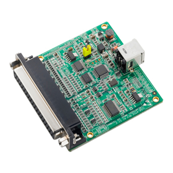
Chapter 2 Installation 2.1 Unpacking After receiving your USB-4702 package, please inspect its contents first. The package should contain the following items: • USB-4702 Module • Shielded USB 2.0 Cable (1.8 m) • Companion CD-ROM (DLL driver included) • User Manual The USB-4702 Module harbors certain electronic components vulnerable to electrostatic discharge (ESD). -
Page 13: Driver Installation
2.2 Driver Installation We recommend you install the software driver before you install the USB-4702 module into your system, since this will guarantee a smooth installation process. The 32-bit DLL driver Setup program for the USB-4702 module is included on the companion CD-ROM that is shipped with your module package. - Page 14 For further information on driver-related issues, an online version of the Device Drivers Manual is available by accessing the following path: Start\Programs\Advantech Automation \Device Manager\Device Driver’s Manual USB-4702 User Manual...
-
Page 15: Hardware Installation
Section 2.2 Driver Installation) After the DLL driver installation is completed, you can now go on to install the USB-4702 module in any USB port that supports the USB 1.1/2.0 standard, on your computer. Please follow the steps below to install the module on your system. - Page 16 Figure 2.1: Unplug or Eject Hardware Dialog Step3: Select “Advantech USB-4702 Device” and press “Stop” Button. Figure 2.2: Stop a Hardware device dialog box Step4: Unplug your USB device from the USB port. Note: Please make sure that you have closed the application before unplugging the USB device, otherwise unex- pected system error or damage may occur.
- Page 17 Signal Connections This chapter provides useful informa- tion on how to connect input and output signals to the USB-4702 via the I/O connectors. Sections include: • Overview • I/O Connectors • Analog Input Connections • Analog Output Connections • Trigger Source Connections...
-
Page 18: Chapter 3 Signal Connections
A good signal connection can avoid unnecessary and costly damage to your PC and other hardware devices. 3.2 I/O Connectors USB-4702 is equipped with one DB-37 connector that facilitates signal connections to the module. 3.2.1 Pin Assignments Warning: The two ground references AGND and DGND should be used separately for their designated purpose. -
Page 19: I/O Connector Signal Description
A signal source without a local ground is also called a “floating source”. It is fairly simple to connect a single-ended channel to a floating signal source. In this mode, USB-4702 provides a reference ground for external floating signal sources. -
Page 20: Differential Input Connections
Low input. Figure 3.3 shows a differential channel connection between a grounded-reference signal source and an input channel on USB-4702. With this connection, the PGIA rejects a common-mode voltage V between the signal source and USB-4702 ground, shown as V in Figure 3.3. -
Page 21: Analog Output Connections (Voltage)
Figure 3.3: Differential Input Channel Connection 3.4 Analog Output Connections (Voltage) USB-4702 provides two analog output channels, AO0 and AO1. Figure 3.4 shows how to make analog output connections on USB-4702. Figure 3.4: Analog Output Channel Connections Chapter 3... -
Page 22: External Trigger Source Connections
USB-4702 board. 3.6 Field Wiring Considerations • When you use USB-4702 to acquire data from outside, noises in the environment might significantly affect the accuracy of your measure- ments if due cautions are not taken. The following measures will be helpful to reduce possible interference running signal wires between signal sources and the USB-4702. - Page 23 Specifications...
-
Page 24: Appendix A Specifications
Small Signal Bandwidth 0.01 Bandwidth for (MHz) 30V max. Input Protection 127 k Input Impedance 100mV Input Common Mode Voltage Gain G = 1 to 20 V/V Accuracy INLE (LSB) ±3 DNLE (LSB) ±1.5 Gain Error 0.15 (%FSR) USB-4702 User Manual... -
Page 25: Analog Output
A.2 Analog Output Channels 12 bits Resolution 0~5 V Output range 150 Hz Max, software-timed Throughput 51 ohm Output Impedance Driving Capability INLE ±12LSB Accuracy DNLE ±5LSB Slew rate 0.7 V/us Dynamic Performance Setting Time 10uS A.3 Non-Isolated Digital Input/Output 8 TTL Input Channels 0.8 V max. - Page 26 USB-4702 User Manual...
Need help?
Do you have a question about the USB-4702 and is the answer not in the manual?
Questions and answers